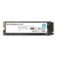
Figure 5 P6000 EVA iSCSI/FCoE controller enclosure (rear view)
10. Power supply 21. Power supply 1
11. 10GbE ports 1–22. Controller 1
12. DP-A and DP-B, connection to back-end (storage)3. Management module status LEDs
13. Serial port4. Ethernet port
14. FP3 and FP4, connection to front end (host or SAN)5. Management module
15. SW Management port6. Controller 2
16. Manufacturing diagnostic port7. Rear UID push button
17. Controller status and fault LEDs8. Enclosure status LEDs
9. Enclosure power push button
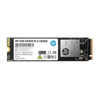
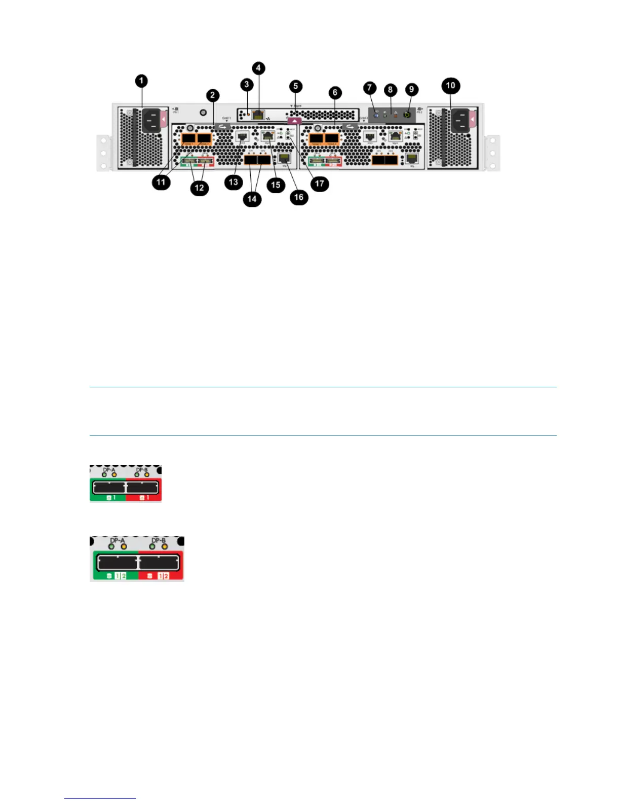
NOTE: The only difference between the P6300 and P6500 controllers is the number indicated
below the SAS data ports (DP-A and DP-B). On the P6300, "1" is displayed (Figure 6 (page 24)).
On the P6500, "1 | 2" is displayed (Figure 7 (page 24)).
Figure 6 P6300 data port numbering
Figure 7 P6500 data port numbering
Controller status indicators
The status indicators display the operational status of the controller. The function of each indicator
is described in Table 3 (page 25). During initial setup, the status indicators might not be fully
operational.
Each port on the rear of the controller has an associated status indicator located directly above it.
Table 1 (page 25) lists the port and its status description for the HSV340. Table 2 (page 25) lists
the port and its status descriptions for the HSV340 FC-iSCSI.
24 P6300/P6500 EVA hardware