• Disables drive enclosures PS 2
• Disables the controller PS 2
PDMs
Depending on the rack, there can be up to eight PDMs mounted in the rear of the rack:
• The PDMs on the left side of the PDM pairs connect to PDU 1.
• The PDMs on the right side of the PDM pairs connect to PDU 2.
Each PDM has seven AC receptacles. The PDMs distribute the AC power from the PDUs to the
enclosures. Two power sources exist for each controller pair and disk enclosure. If a PDU fails, the
system will remain operational.
CAUTION: The AC power distribution within a rack ensures a balanced load to each PDU and
reduces the possibility of an overload condition. Changing the cabling to or from a PDM could
cause an overload condition. HP supports only the AC power distributions defined in this user
guide.
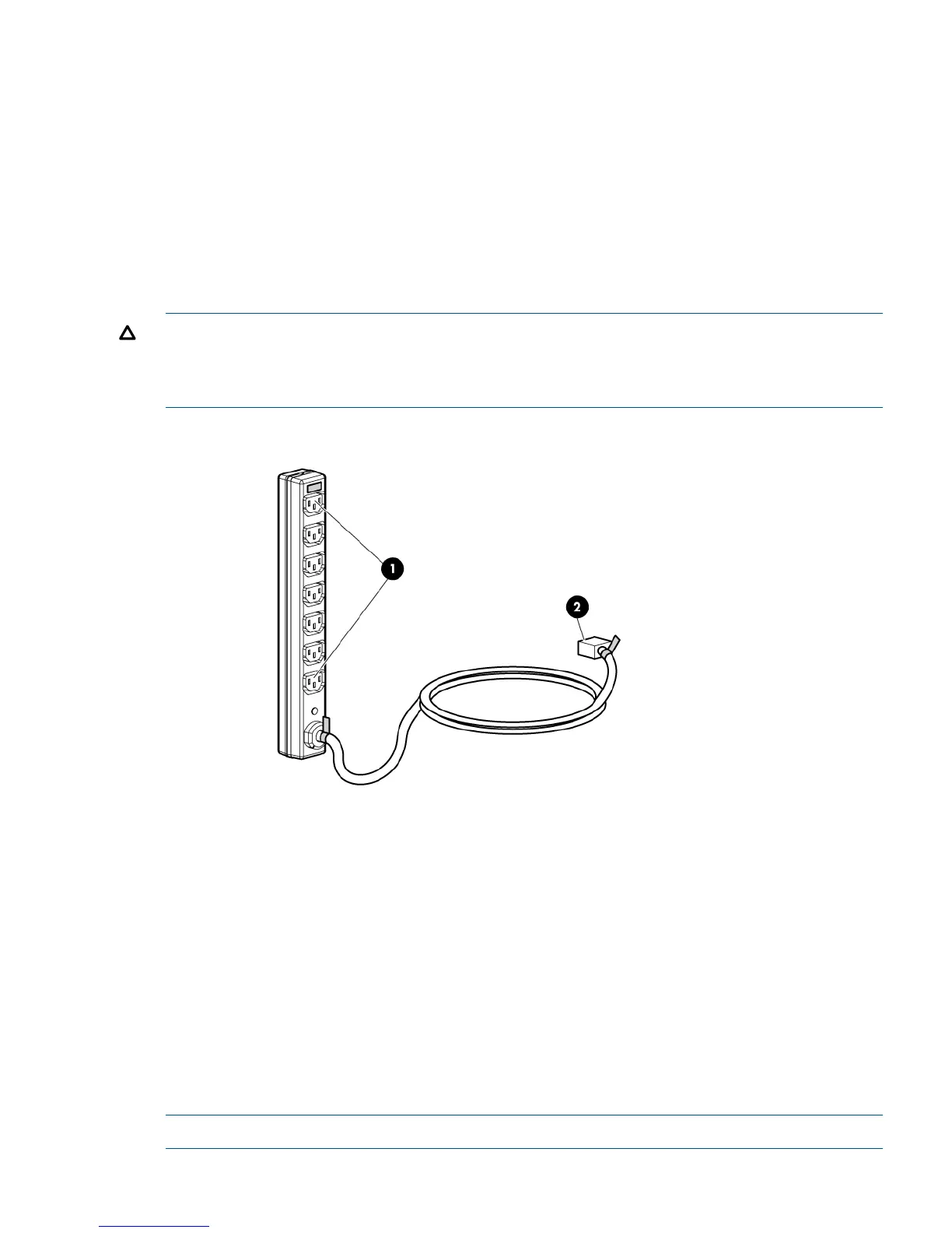
Figure 13 Rack PDM
1. Power receptacles
2. AC power connector
Rack AC power distribution
The power distribution in a rack is the same for all variants. The site AC input voltage is routed to
the dual PDU assembly mounted in the bottom rear of the rack. Each PDU distributes AC to a
maximum of four PDMs mounted in pairs on the left vertical rail (see Figure 14 (page 32)).
• PDMs 1–1 through 1–4 connect to receptacles A through D on PDU A. Power cords connect
these PDMs to the left power supplies on the disk enclosures (disk PS 1) and to the left power
supply on the controller enclosure (controller PS 1).
• PDMs 2–1 through 2–4 connect to receptacles A through D on PDU B. Power cords connect
these PDMs to the right power supplies on the disk enclosures (disk PS 2) and to the right
power supply on the controller enclosure (controller PS 2).
NOTE: The locations of the PDUs and the PDMs are the same in all racks.
Power distribution units 31