10. Remove one screw (callout 1).
Figure 1-242 Remove the HVPS (7 of 11)
1
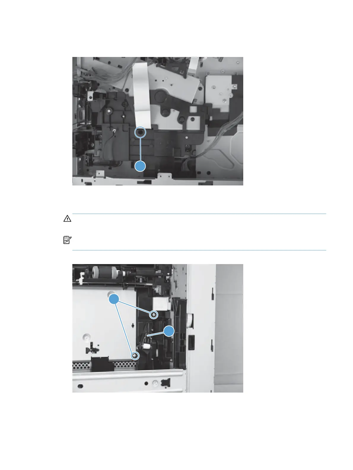
11. Place the product face-side up. Remove two screws (callout 1), and then remove the positioning
guide (callout 2).
CAUTION: When you place the product face-side up, do not damage the rear-door link arm on
the left side of the product.
NOTE: The positioning guide might appear to still be fastened to the product. You might have to
use slight force to separate it from the product.
Figure 1-243 Remove the HVPS (8 of 11)
1
2
ENWW
Removal and replacement procedures
163
 Loading...
