Spanning-Tree Operation
802.1D Spanning-Tree Protocol (STP)
In figure 6-20:
• Port A1 and Trk1 (trunk 1; formed from ports 2 and 3) are redundant
fast-uplink STP links, with trunk 1 forwarding (the active link) and
port A1 blocking (the backup link). (To view the configuration for port
A1 and Trk1, see figure
6-18 on page 6-37.)
• If the link provided by trunk 1 fails (on both ports), then port A1 begins
forwarding in fast-uplink STP mode.
• Ports A5, A6, and A24 are connected to end nodes and do not form
redundant links.
CLI: Viewing and Configuring Fast-Uplink STP
Using the CLI to View Fast-Uplink STP. You can view fast-uplink STP
using the same
show commands that you would use for standard STP opera-
tion:
Syntax:
show spanning-tree
Lists STP status.
Syntax:
show spanning-tree config
Lists STP configuration for the switch and for individual
ports.
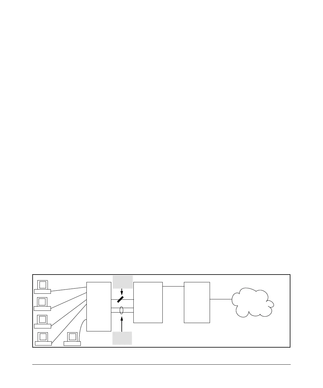
For example, figures 6-21 and 6-22 illustrate a possible topology, STP status
listing, and STP configuration for a switch with:
■ STP enabled and the switch operating as an Edge switch
■ Port A1 and trunk 1 (Trk1) configured for fast-uplink STP operation
■ Several other ports connected to PC or workstation end nodes
3400cl or
5300xl
switch
Operating
as an Edge
Switch
Interior
Switch
with STP
Enabled
STP
Root
Device
Port
Trunk
STP
Block
LAN
Figure 6-21. Example Topology for the Listing Shown in Figure 6-22
6-39
 Loading...


