Router Redundancy Using XRRP
Overview of XRRP Operation
XRRP During Normal Router Operation
For each router, XRRP defines a virtual router, using the IP address that you
have configured on the router interface, and for which XRRP assigns a virtual
MAC address based on the Protection Domain ID and the XRRP router number
of the router that owns the interface. The configuration is done for each VLAN
on which you wish to use XRRP for router redundancy, so the router interfaces
for each virtual router must be in the VLAN. Each Protection Domain contains
two routers, but within a single VLAN, up to 16 Protection Domains (16 pairs
of routers) can be configured.
In the situation in which both routers in the Protection Domain are operating
normally, none of the VLANs are down, each physical router behaves as the
Master of all of its XRRP virtual router interfaces. The Master and Owner of
each interface is the same.
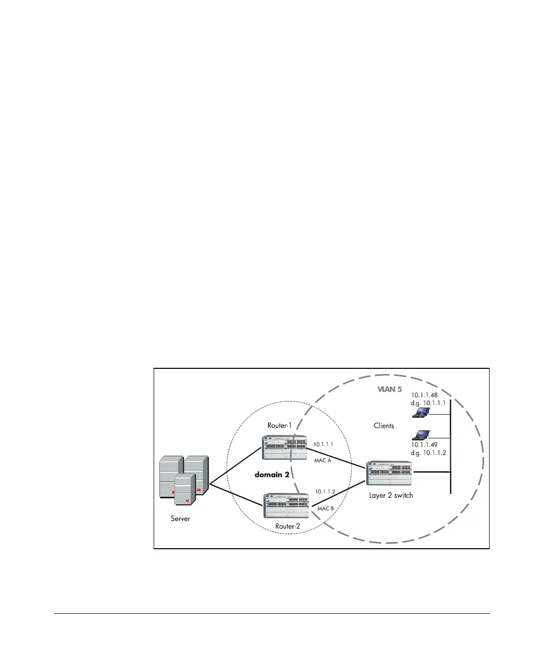
In the example shown in figure 12-2, the XRRP configuration is done in
VLAN 5. For Domain 2, Router-1 is given the IP address of 10.1.1.1 and Router-
2 is given the address 10.1.1.2. XRRP assigns MAC addresses MAC-A to Router-
1 and MAC-B to Router-2. Note that the clients in figure 2 use both of the virtual
router as their default gateways. Client 10.1.1.48 is configured to use virtual
router 10.1.1.1 as its default gateway, and client 10.1.1.49 is configured to use
virtual router 10.1.1.2. In this way XRRP can be used to provide load balancing
as long as both virtual routers are operating normally. The virtual routers will
route packets passed to them, respond to IP ARP requests and PING packets,
and perform the other router functions.
Figure 12-2. XRRP During Normal Router Operation
12-4
 Loading...


