Spanning-Tree Operation
802.1D Spanning-Tree Protocol (STP)
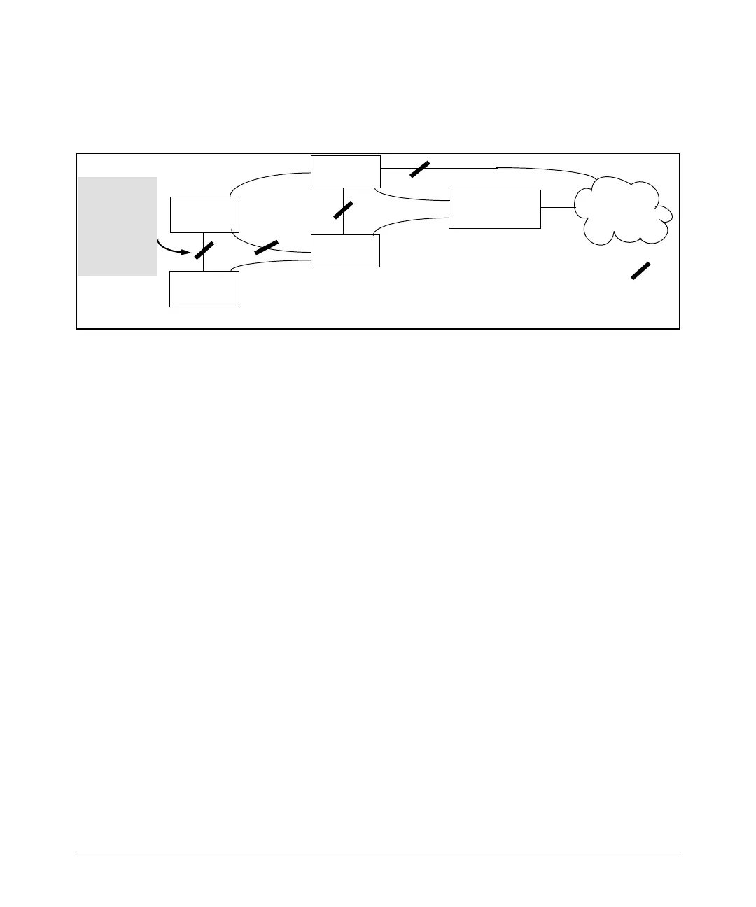
■ Edge switches cannot be directly linked together using fast-uplink ports.
For example, the connection between switches 4 and 5 in figure 6-14 is
not allowed for fast-uplink operation.
Switch 4
(5304-Edge)
Switch 3
Switch 1
(Root)
Switch 2
Link blocked by STP:
LAN
Switch 5
(5304-Edge)
The ports
that make up
this link
cannot be
configured
as fast-
uplink ports.
Figure 6-14. Example of a Disallowed Connection Between Edge Switches
■ Apply fast-uplink only on the uplink ports of an edge switch. For example,
on switch “4” (an edge switch) in figure 6-14 above, only the ports
connecting switch “4” to switches “2” and “3” are upstream ports that
would use fast uplink. Note also that fast uplink should not be configured
on both ends of a point-to-point link, but only on the uplink port of an edge
switch.
■ Ensure that the switch you intend as a backup root device will in fact
become the root if the primary root fails, and that no ports on the backup
root device are configured for fast-uplink operation. For example, if the
STP Priority is the same on all switches—default: 32768—then the switch
with the lowest MAC address will become the root switch. If that switch
fails, then the switch with the next-lowest MAC address will become the
root switch. Thus, you can use
STP Priority to control which switch STP
selects as the root switch and which switch will become the root if the
first switch fails.
■ Fast-Uplink STP requires a minimum of two uplink ports.
Menu: Viewing and Configuring Fast-Uplink STP
You can use the menu to quickly display the entire STP configuration and to
make any STP configuration changes.
6-33
 Loading...


