Access Control Lists (ACLs) for the Series 5300xl Switches
Configuring and Assigning an ACL
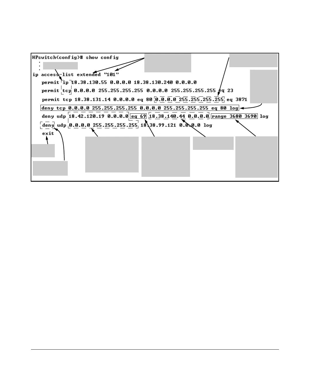
For example, figure 9-9 shows how to interpret the entries in an extended ACL.
Optional Source UDP or
TCP Operator and Port
Number
In this case, the ACL
specifies UDP port 69
packets coming from the
source IP address.
Protocol Types
End-of-List
Marker
Source IP Addresses and
Masks.
Upper entry denies certain
UDP packets from a single
host. Lower entry denies all
UDP packets from all hosts.
Optional Destination
UDP or TCP Operator
and Range of Port
Numbers
In this case, the ACL
specifies UDP port
numbers 3680-3690.
Destination IP
Address and Mask
ACE Action
(permit or deny)
ACL List Heading with
List Type and ID String
(Name or Number)
Specifies all destination
IP addresses.
Denies TCP
Port 80
traffic to any
destination
from any
source.
Figure 9-9. Example of a Displayed Extended ACL Configuration
ACL Configuration Factors
The Sequence of Entries in an ACL Is Significant
When the switch uses an ACL to determine whether to permit or deny a packet
on a particular VLAN, it compares the packet to the criteria specified in the
individual Access Control Entries (ACEs) in the ACL, beginning with the first
ACE in the list and proceeding sequentially until a match is found. When a
match is found, the switch applies the indicated action (permit or deny) to the
packet. This is significant because, once a match is found for a packet,
subsequent ACEs in the same ACL will not be used for that packet, regardless
of whether they match the packet.
For example, suppose that you have applied the ACL shown in figure 9-10 to
inbound traffic on VLAN 1 (the default VLAN):
9-29

 Loading...


