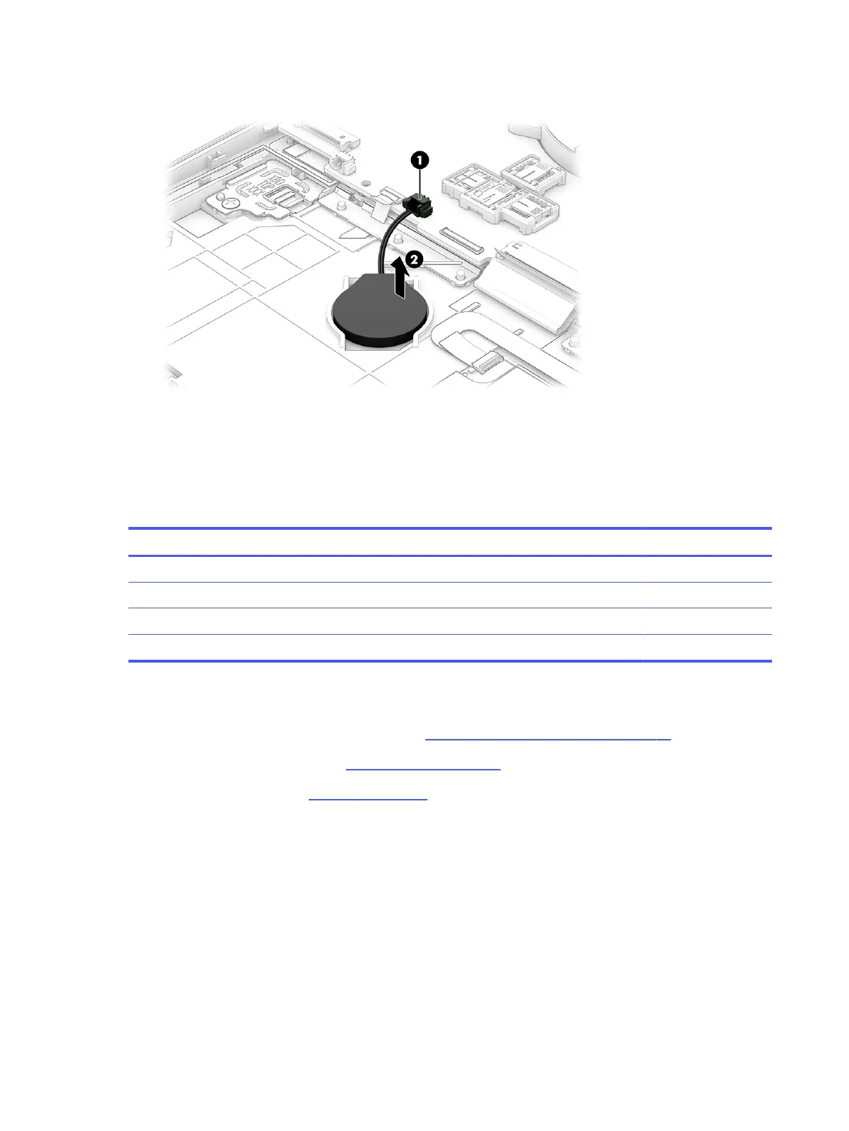
2. Detach the RTC battery (2) from the computer. The RTC battery is attached with adhesive.
To install the RTC battery, reverse this procedure.
Card reader board
To remove the card reader board, use this procedure and illustration.
Table 5-7
Card reader board description and part number
Description Spare part number
Card reader board N12914-001
Card reader board cable (included in Cable Kit) N56092-001
Card reader insert (included in Plastic Kit) N06911-001
Support brackets (available in Bracket Kit) M21855-001
Before removing the card reader board, follow these steps:
1. Prepare the computer for disassembly (see Preparation for disassembly on page 37).
2. Remove the bottom cover (see Bottom cover on page 37).
3. Remove the battery (see Battery on page 39).
Remove the card reader board:
1. Remove the two Phillips M2.0 × 5.0 screws (1) that secure the battery support bracket to the
computer.
46
Chapter 5 Removal and replacement procedures for authorized service provider parts

 Loading...