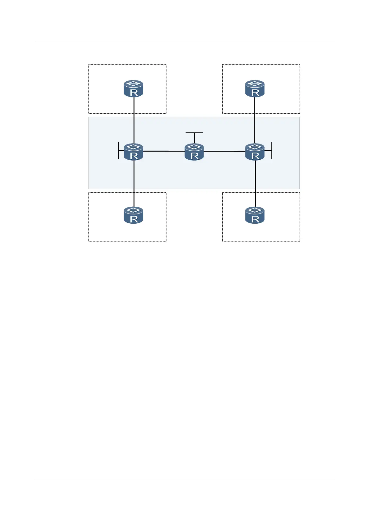
Figure 3-2 BGP/MPLS IP VPN networking diagram
AS: 65440
VPN-B
CE4
PE1
P
AS: 65430
VPN-A
CE3
Eth1/0/0
10.3.1.1/24
Eth1/0/0
10.3.1.2/24
AS: 65420
VPN-B
CE2
AS: 65410
VPN-A
CE1
Eth1/0/0
10.1.1.1/24
Eth1/0/0
10.1.1.2/24
Eth2/0/1
172.1.1.1/24
Eth2/0/0
172.2.1.1/24
AS: 100
PE2
Loopback1
1.1.1.9/32
Loopback1
3.3.3.9/32
Eth1/0/0
10.4.1.1/24
Eth1/0/0
10.2.1.1/24
Eth2/0/0
10.4.1.2/24
Eth2/0/0
10.2.1.2/24
Eth1/0/0
172.1.1.2/24
Eth2/0/1
172.2.1.2/24
MPLS backbone
Loopback1
2.2.2.9/32
Configuration Roadmap
The configuration roadmap is as follows:
1. Configure OSPF on the backbone network to enable interworking between PEs.
2. Configure the basic MPLS functions and MPLS LDP on the PEs, and establish the MPLS
LSPs between the PEs.
3. Configure MP IBGP to exchange the VPN routing information between the PEs.
4. Configure the VPN instance on the PE connected with the CE in the backbone network,
and bind the PE interface connected with the CE to the corresponding VPN instance.
5. Configure EBGP between the CE and the PE to exchange VPN routing information.
Data Preparation
To configure BGP/MPLS IP VPN, you need the following data:
l MPLS LSR-IDs on the PEs and the Ps
l RDs of VPN-A and VPN-B
l VPN targets of VPN-A and VPN-B
Procedure
Step 1 Configure an IGP on the MPLS backbone to allow the PEs and the Ps to reach each other.
# Configure PE1.
Huawei AR1200 Series Enterprise Routers
Configuration Guide - VPN 3 BGP MPLS IP VPN Configuration
Issue 01 (2012-04-20) Huawei Proprietary and Confidential
Copyright © Huawei Technologies Co., Ltd.
151

 Loading...


