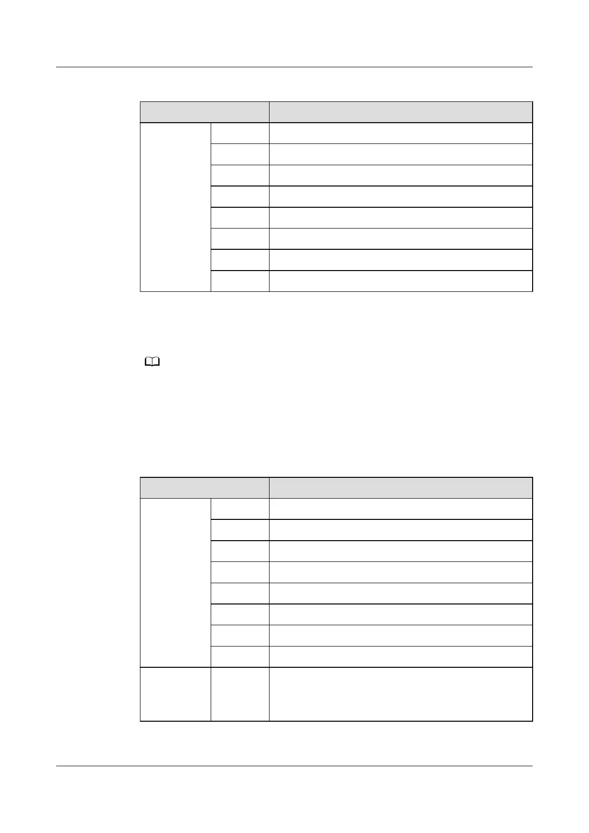
Table 3-18 COM4/CAN port pin denitions
Item Description
Pin
sequence
Pin1 RS485+
Pin2 RS485-
Pin3 -
Pin4 RS485+
Pin5 RS485-
Pin6 -
Pin7 CAN_H
Pin8 CAN_L
The following provides the AIDI_1, AIDI_2 and AIDI_3 ports pin
denitions.
● Pins 1, 2, 4, and 5 identify sensor types.
● Pin 3 and Pin 8 are power output ports.
● Pin 6 and Pin 7 collect sensor data. Pin 7 can detect current type sensors (4–20 mA). Pin
6 and Pin 7 can detect the output status of passive dry contact type sensors. Pin 3 and
Pin 7 can detect temperature sensors.
Table 3-19 AIDI_1, AIDI_2 and AIDI_3 ports pin denitions
Item
Description
Pin
sequence
Pin1 Type_1
Pin2 Type_2
Pin3 12V DC
Pin4 Type_3
Pin5 Type_4
Pin6 DI-
Pin7 DI+
Pin8 GND
Indicator Green
indicator
Power output indicator
● Steady on: The 12 V DC output is normal.
● O: No 12 V DC output is provided.
FusionModule500 Smart Mini Data Center
User Manual 3 System Architecture
Issue 02 (2020-12-25) Copyright © Huawei Technologies Co., Ltd. 37