HUAWEI NetEngine40E Universal ServiceRouter
Hardware Description
5 NE40E-8 Chassis Overview
Huawei Proprietary and Confidential
Copyright © Huawei Technologies Co., Ltd.
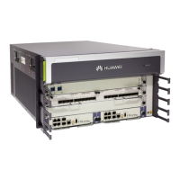
Figure 5-11 Front panel of the fan module on the NE40E-8
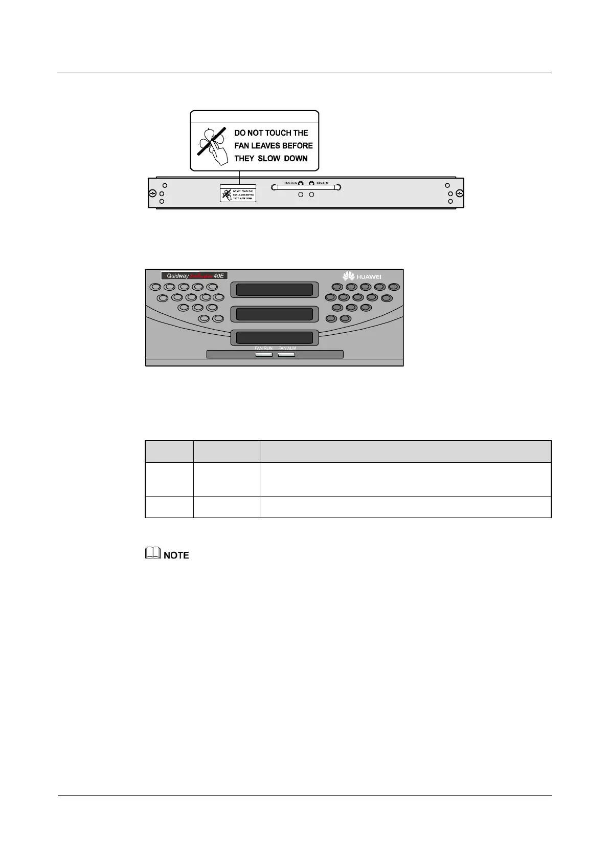
Figure 5-12 Plastic panel of the fan module on the NE40E-8
Table 5-8 shows the indicators of the fan module on the plastic panel.
Table 5-8 Description of the indicators of the NE40E-8 fan module
If this indicator blinks at a frequency of 1 Hz, the fan module is
working normally.
If this indicator is on, the FAN is working abnormally.
When the FCB fails, the fan board cannot receive the speed regulation or control signal. Thus, The fan
board operates at full speed and the alarm indicator is turned on.
5.3.3 Air Filter
The air filters and the fan modules are located separately. The NE40E-8 has two air filters.
One is located behind the plastic panel of the air intake frame, and the other is behind the
plastic panel of the power supply. Figure 5-13 shows the air filter on the air intake frame.