HUAWEI NetEngine40E Universal ServiceRouter
Hardware Description
3 NE40E-X8 Chassis Overview
Huawei Proprietary and Confidential
Copyright © Huawei Technologies Co., Ltd.
Figure 3-4 Slot layout on the NE40E-X8
1
2 3 4 5 6 7
L
P
U
L
P
U
L
P
U
L
P
U
L
P
U
L
P
U
L
P
U
S
R
U
S
R
U
811
L
P
U
S
F
U
9 10
1
2 3 4 5 6 7 8119 10
An interface is numbered in the format of Slot number/card number/Port number
Slot number:On the NE40E-X8, the slots of LPUs are numbered from 1 to 8. The slot number increases
from left to right facing the front panel of the NE40E (there are corresponding marks on the panel).
Card number:the cards of LPUs are numbered from top to bottom and from right to left beginning with
0. If there is no card on a board, the card number is set to 0.
Port number:the ports of LPUs are numbered from left to right and from top to bottom beginning with
0.
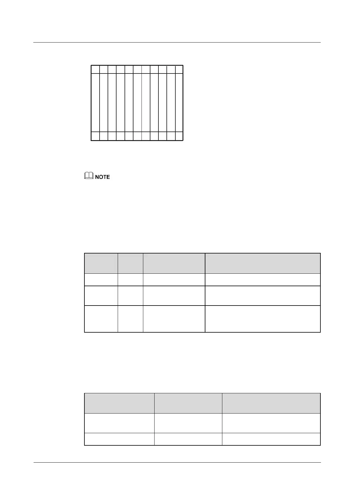
Table 3-1 describes the slot layout on the NE40E-X8.
Table 3-1 Board distribution in the board cage of the NE40E-X8
These slots are used to hold LPUs.
These slots hold SRUs in 1:1 backup
mode.
The slot is used to hold an SFU, which,
together with two switch fabric units on the
SRUs, works in 2+1 load balancing mode.
3.1.6 System Configuration
This section describes the system configuration and physical parameters of the NE40E-X8.
Table 3-2 System configuration list of the NE40E-X8