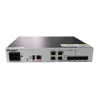
HUAWEI NetEngine40E Universal ServiceRouter
Hardware Description
Huawei Proprietary and Confidential
Copyright © Huawei Technologies Co., Ltd.
Precautions for the overload-caused burnt optical module
When using an OTDR to test the connectivity or the attenuation of optical signals,
disconnect the optical connector from the optical module. Otherwise, the optical module
is probably burnt.
When performing a self-loop test, use an optical attenuator. Do not loosen the optical
connector instead.
It is required that a long-distance optical module input optical power smaller than -7
dBm. If the input optical power is larger than -7 dBm, you need to add an optical
attenuator. For example, if the transmiting optical power is X dBm and the optical
attenuation is Y dB, the receiving optical power is X-Y, which must be smaller than
-7dBm (X-Y<-7 dBm).
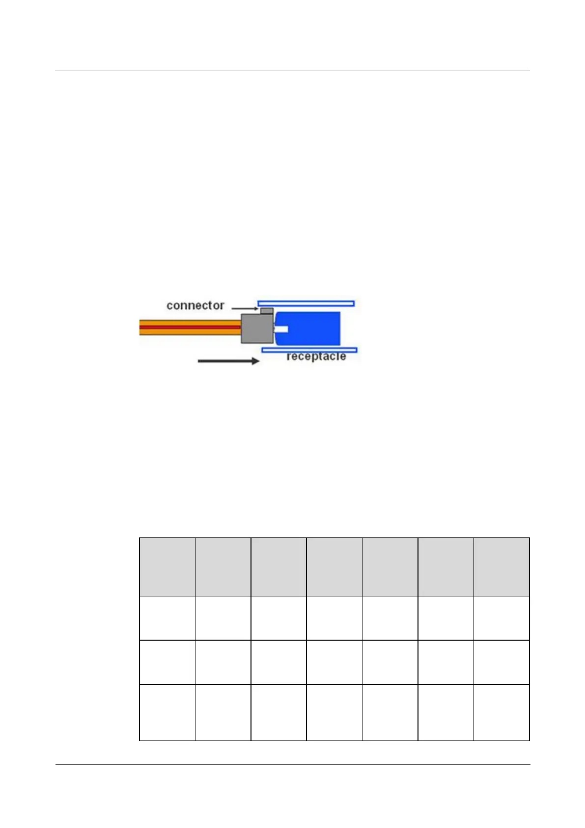
Other precautions
The optical connector should be horizontally inserted in the receptacle to avoid damages
to the receptacle.
Mixed use of multi-mode and single-mode optical fibers is prohibited. Otherwise, faults
such as signal loss may occur.
D.2 155 Mbit/s SFP/eSFP Optical Module
The STM-1 SFP optical module, with the transmission rate ranging from 100 Mbit/s to 155
Mbit/s, the wavelength being 1310 nm or 1550 nm, and the transmission distance ranging
from 2 km ( 1.24 mi. ) to 100 km ( 62.14 mi. ), can be applied to the STM-1/OC-3 POS
interface, ATM interface, or FE optical interface .
Table D-1 lists the currently available 155 Mbit/s SFP/eSFP optical modules.
Table D-1 155 Mbit/s SFP/eSFP Optical Modules
Transmis
sion
Distance(
km)
Preferred
When
performin
g a