UPS5000-E-(50 kVA-300 kVA)
User Manual (50 kVA Power Modules)
Copyright © Huawei Technologies Co., Ltd.
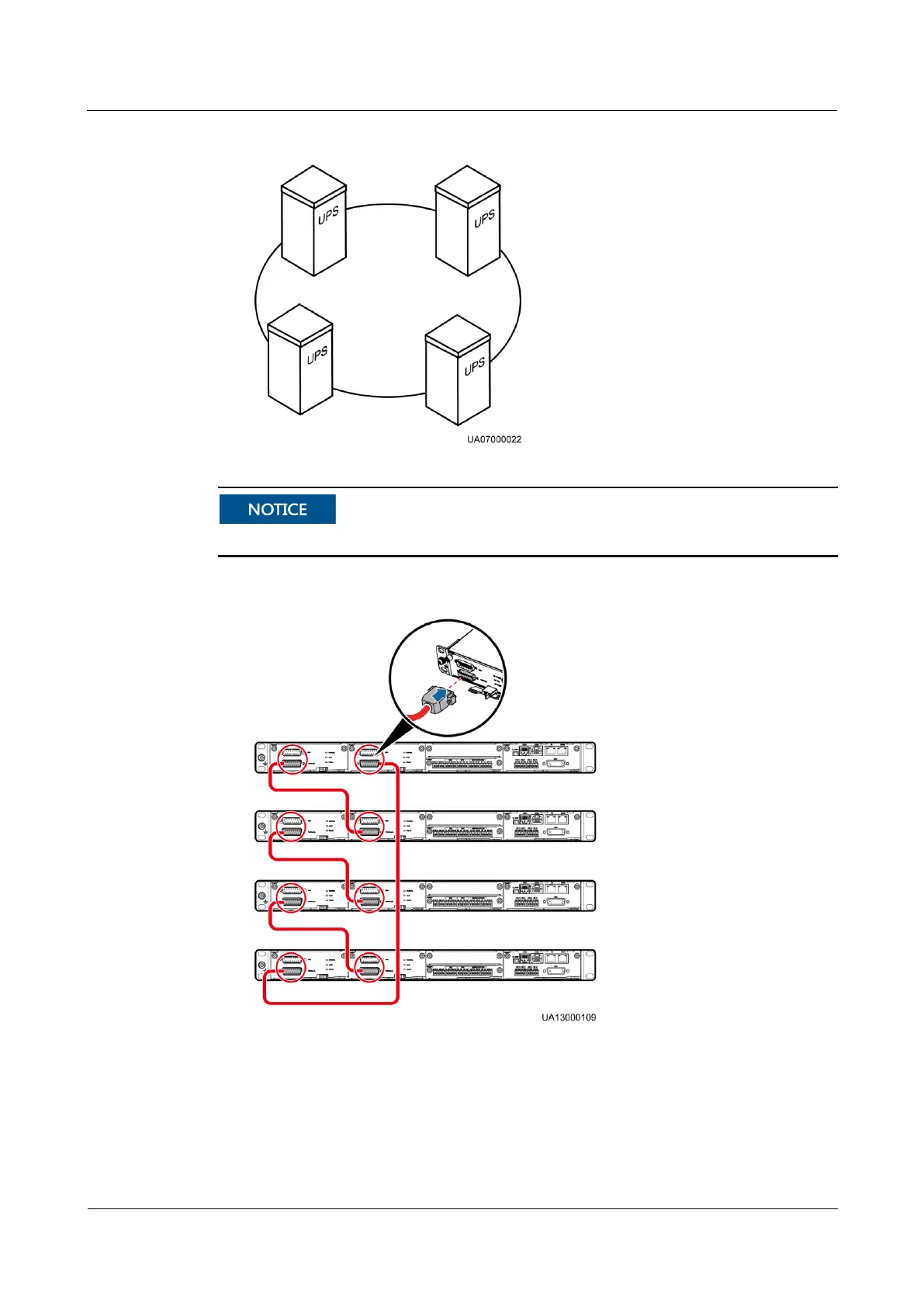
Figure 3-104 Topology diagram of an N+X parallel system
Figure 3-105 shows only control modules. Each control module represents a single UPS.
Figure 3-105 Connecting signal cables in a parallel system consisting of four UPSs
In a dual-bus system, you need to connect cables to BSC ports on the UPSs. Figure
3-106 shows the cable connections for a dual-bus system containing two master systems.