262
4.2 Settings of Parameters for Vibration Suppress Control
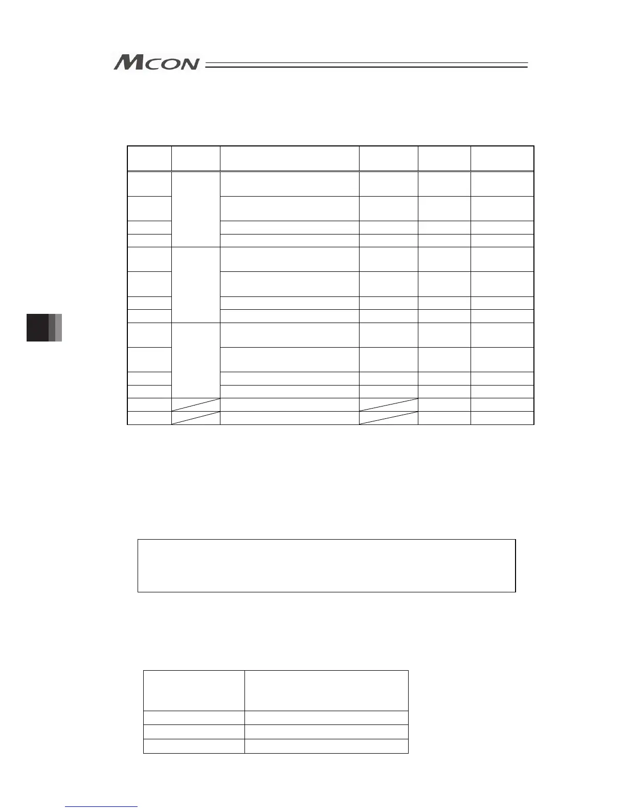
Set the parameters associated with vibration suppress control, which are listed in the table
below.
Parameter
No.
Parameter
Set No.
Parameter Name Unit Default Input Range
97
Damping characteristic
coefficient 1
Rate 10 0 to 1000
98
Damping characteristic
coefficient 2
Rate 1000 0 to 1000
99 Natural frequency 1/1000Hz 10000 500 to 30000
100
1
Notch filter gain Rate 9990 1 to 20000
101
Damping characteristic
coefficient 1
Rate 10 0 to 1000
102
Damping characteristic
coefficient 2
Rate 1000 0 to 1000
103 Natural frequency 1/1000Hz 10000 500 to 30000
104
2
Notch filter gain Rate 9990 1 to 20000
105
Damping characteristic
coefficient 1
Rate 10 0 to 1000
106
Damping characteristic
coefficient 2
Rate 1000 0 to 1000
107 Natural frequency 1/1000Hz 10000 500 to 30000
108
3
Notch filter gain Rate 9990 1 to 20000
109 Default vibration suppress No. 0 0 to 3
110 Stop method at servo OFF 0 0, 1
[1] Damping characteristic coefficient 1, 2 (Parameter No.97, 98, 101, 102, 105, and 106)
In this section, do not change.
[2] Natural frequency [1/1000Hz] (Parameter No.99, 103 and 107)
Set the natural frequency of the load measured. It can be input directly to the parameter
from the frequency analysis tool for anti-vibration control included in the PC software if the
tool is already used. [Refer to the Instruction Manual of the RC PC software.]
Set the specific frequency of the loaded object close to the setting so a higher anti-vibration
performance can be obtained.
[Reference] Other vibration measuring methods
• Use of measuring instrument such as vibration meter and acceleration
pickup
• Calculation from video image data
[3] Notch filter gain (Parameter No.100, 104 and 108)
Set the notch filter gain following the table below in response to the measured specific
frequency of the loaded object. See the table below for reference. Provide fine adjustment if
overshooting occurs.
If the notch filter gain setting is too high, overshooting would occur during the settling time.
If the notch filter gain setting is too low, undershooting would occur during the settling time.
Measured Natural
Frequency [Hz]
Setting Value of Notch Filter Gain
0.5 9900
1 9980
2 to 30 9990
Chapter 4 Vibration Suppress Control Function