333
9.4 Driver Alarm
9.4.1 Alarm Level
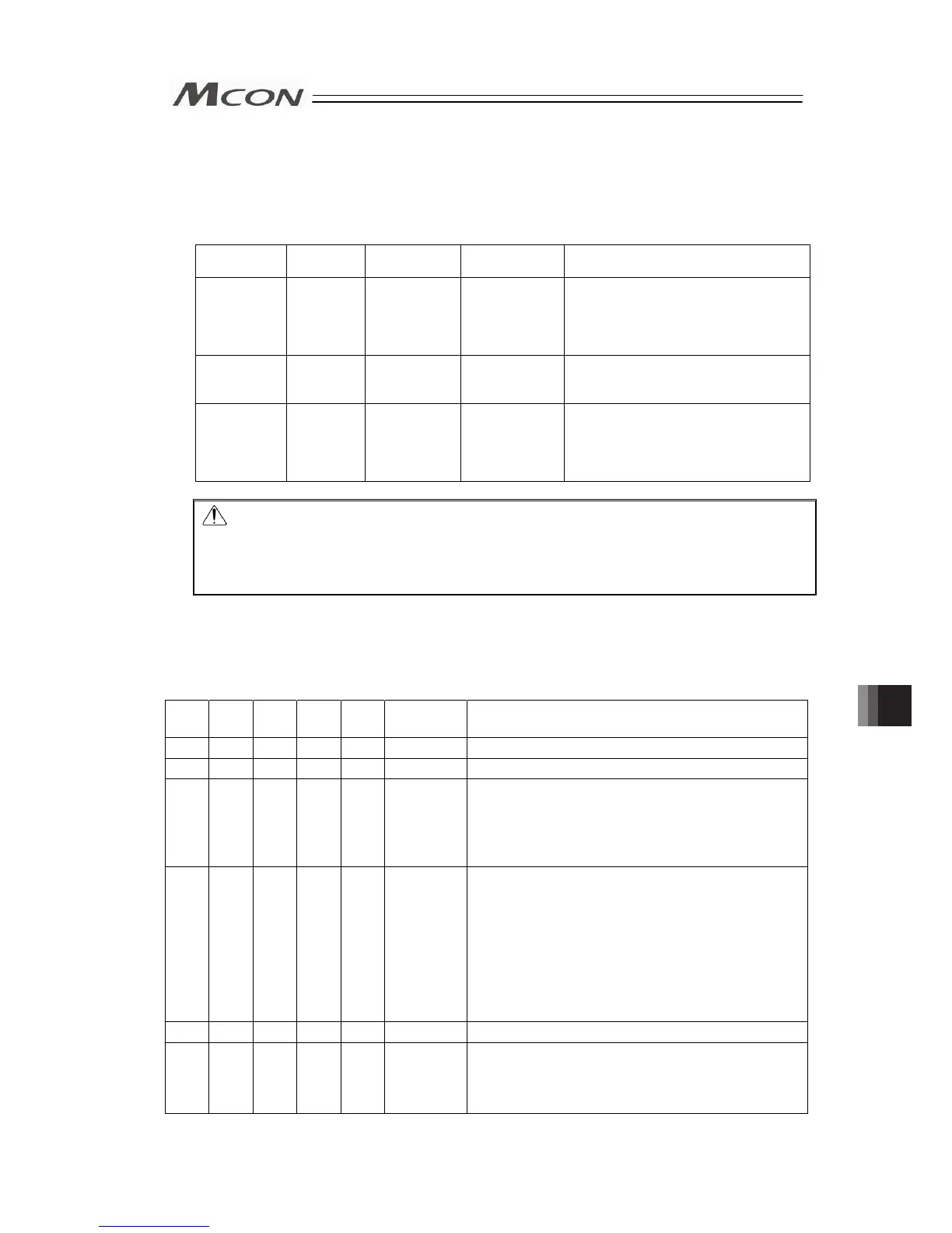
The alarms are classified to 3 types of levels by the content of the error.
Alarm level
SYS I / II
LED
*ALM signal
Status when an
error occurred
Cancellation method
Message Green Light
is turned
ON.
No output No stop Alarm of maintenance output such as
battery voltage drop or the teaching tool
such as PC software
[Refer to Instruction Manual of each tool
for details.]
Operation
release
Red Light is
turned ON.
Output Servo OFF after
deceleration to
stop
Reset the alarm by the PIO or teaching
tool.
Cold start Red Light is
turned ON.
Output Servo OFF after
deceleration to
stop
Software reset or power reconnection by
teaching tool.
Home return is required for any actuators
of other than simple absolute
specification.
Caution: Reset each alarm after identifying and removing the cause.
If the cause of the alarm cannot be removed or when the alarm cannot be reset
after removing the cause, please contact IAI.
If the same error occurs again after resetting the alarm, it means that the cause
of the alarm has not been removed.
9.4.2 Simple Alarm Code
Simple alarm codes are read into the complete position register (PM8 to PC1) in Simplified
Direct Value, Positioner 1, Positioner 2, Positioner 5 and each mode of remote I/O when an
alarm is generated.
{: ON z: OFF
*ALM
ALM8
(PM8)
ALM4
(PM4)
ALM2
(PM2)
ALM1
(PM1)
Binary Code Description: Alarm code is shown in ( ).
{ z z z z
– Normal
z z z z {
1 Collision Detection (0DF)
z z z { z
2
Software reset during servo ON (090)
Position number error during teaching (091)
PWRT signal detected during movement (092)
PWRT signal detected before completion of home
return (093)
z z z { {
3
Move command during servo OFF (080)
Position command in incomplete home return (082)
Absolute position move command when home
return is not yet completed (083)
Movement command during home return operation
(084)
Position No. error during movement (085)
Position command information data error (0A3)
Command deceleration error (0A7)
z z { z z
4 Mismatched PCB (0F4)
z z { { z
6
Parameter data error (0A0)
Parameter data error (0A1)
Position data error (0A2)
Unsupported motor/encoder type (0A8)
(Note) *ALM Signal is an active low signal. It is ON when the power is applied to the controller, and
turns OFF when the signal is output.
Chapter 9 Troubleshooting