113
3.4.5 Control Signals for Positioner 1 Mode
Caution: This mode is not applicable for CompoNet.
Operation is performed by indicating a position number from the operation modes of the
position data set in the position table.
The settable No. of position data items is max 256 points.
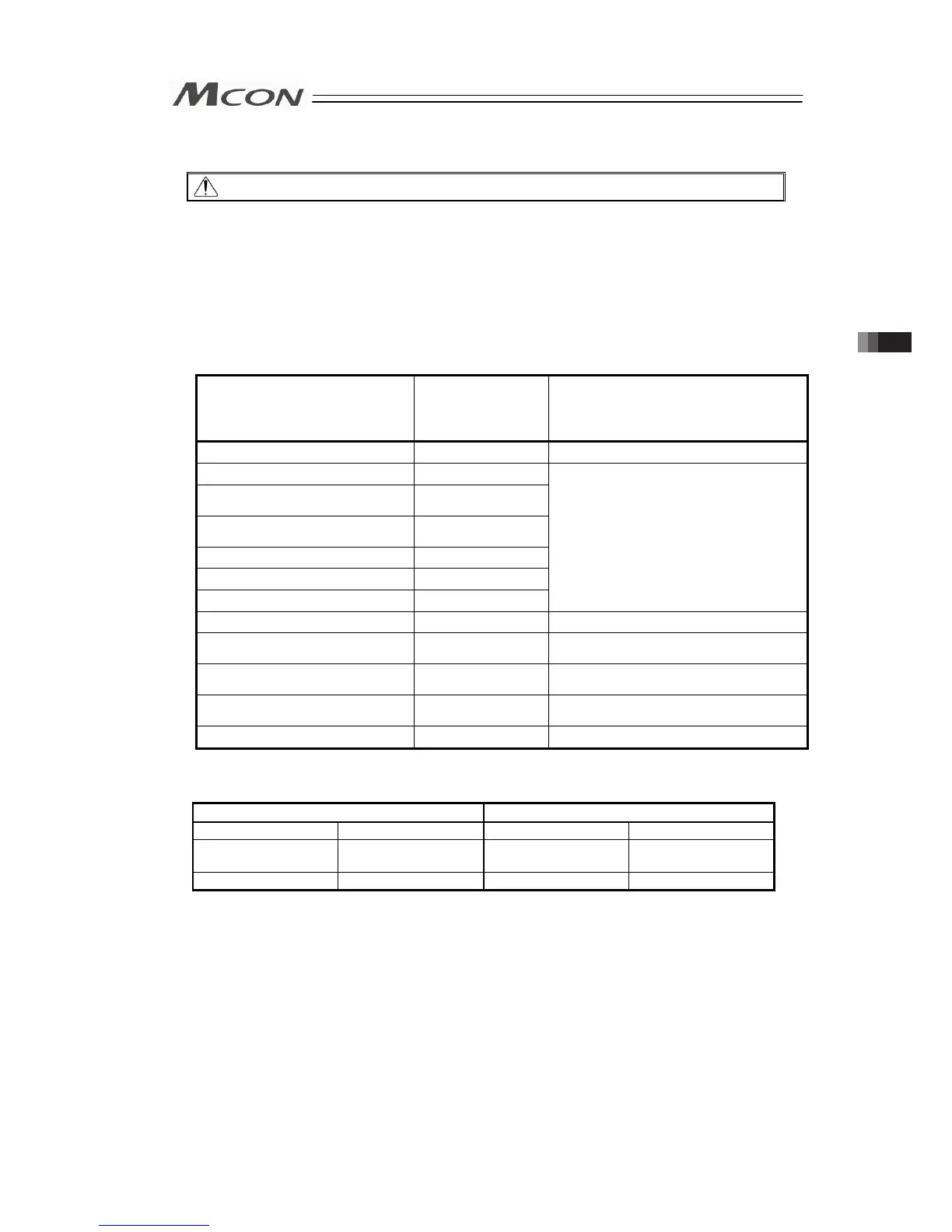
The main functions of ROBO Cylinder capable to control in this mode are as described in the
following table.
ROBO cylinder function
{: Direct control
△: Indirect control
×: Disabled
Remarks
Home-return operation
{
Positioning operation △
Speed and acceleration/
deceleration setting
△
Separate settings for acceleration
and deceleration
△
Pitch feed (incremental) △
Pressing operation △
Speed change during movement △
These items must be set in the position
data table.
Pause
{
Zone signal output △
These items must be set in the
parameters.
Position zone signal △
These items must be set in the position
data table.
Vibration control △
This feature is limited only to the servo
motor type actuators.
PIO pattern selection
×
(1) PLC Address Composition
(m is PLC input and output top word address for each axis number)
PLC → MCON (PLC Output) MCON → PLC (PLC Input)
Cannot be used. m to m+1 Current Position m to m+1
Specified Position No. m+2
Completed Position No.
(Simple Alarm Code)
m+2
Control Signal m+3 Status Signal m+3
[Refer to Section 3.4.2 for the address maps for each Fieldbus.]
3.4 Fieldbus Type Address Map

 Loading...


