49
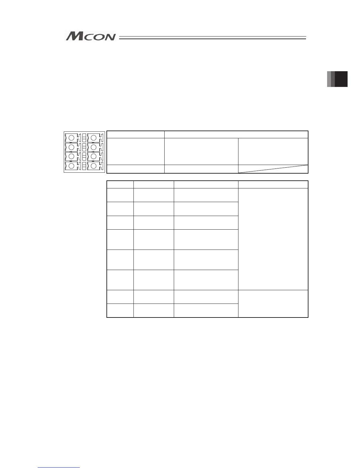
2.3.2 Wiring Layout of System I/O Connector
The connector consists of the emergency stop input for the whole controller, changeover of the
operation modes (AUTO/MANU) externally and the external regenerative resistor connection
terminals.
Insert the wires to the enclosed connector (plug). Strip the sheath of the applicable wires for
10mm and insert them to the connector. Push a protrusion beside the cable inlet with a small
slotted screwdriver to open the inlet. Once the cable is inserted, take the slotted screwdriver
OFF the protrusion to fix the cable to the terminal.
Connector Name System I/O Connector
Cable Side FMCD1.5/4-ST-3.5 Enclosed in standard
package
Manufactured by
PHOENIX CONTACT
1
2
3
4
6
7
8
5
Controller Side
MCDN1.5/4-G1-3.5P26THR
Pin No. Signal Name Description Applicable cable diameter
1 EMG+24V
+24V power output for
emergency stop
2 S2
For external emergency
stop signal input
3 S1
For external emergency
stop signal output
4 EMG-
Emergency Stop Input
(available for all the
slots)
5 AUTO/MANU+
For operation mode
(AUTO/MANU)
switchover
6 AUTO/MANU-
Operation mode
(AUTO/MANU)
switchover signal input
KIV0.5 to 0.2mm
2
(AWG20 to 24)
7 RB+
Regenerative resistor
connection +
Front view of
connector on
controller side
8 RB-
Regenerative resistor
connection -
Dedicated regenerative
resistor connection
Chapter 2 Wiring