24
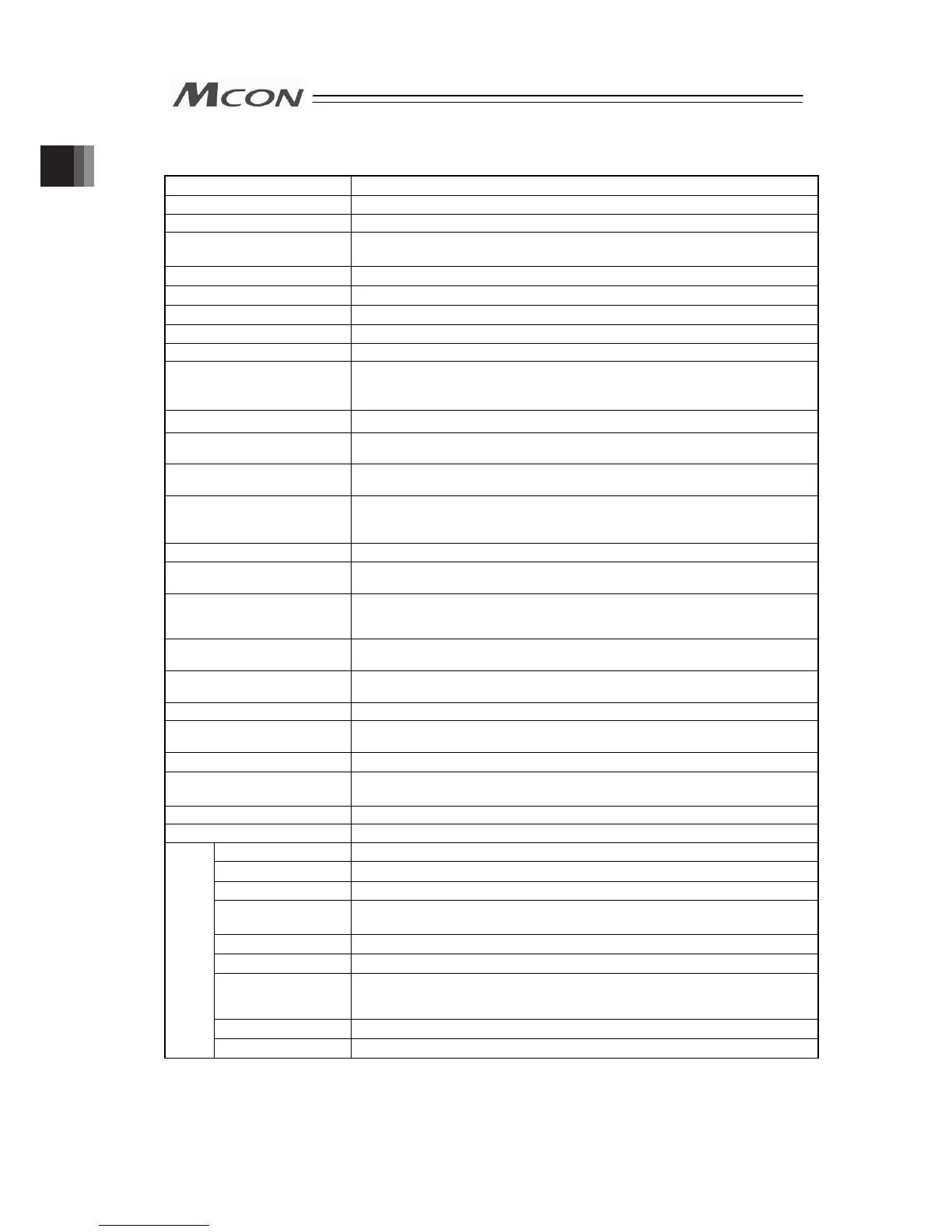
1.2 List of Basic Specifications
Specification Item Details of Specifications
Number of Controlled Axes Max.8 axis
Control/Motor Power Supply Voltage 24V DC ±10%
Current Consumption of Brake
Release Power
0.15A×Number of axes
Control Power Current Consumption
1.0A
Control Power In-Rush Current
MAX. 5A 30ms or less
Motor Current Consumption Refer to Section < Motor Current Consumption >
Motor Power In-Rush Current Number of slots × MAX. 10A 5ms or less
Controller Heat Generation MAX. 26W
Control System
Driver for Pulse Motor : Weak field-magnet vector control
Driver for Servo Motor : Vector control
Driver for Brushless DC Motor : Square wave drive
Encoder Resolution
Refer to Section <Encoder Resolution>
Motor / Encoder Cable Length
MAX. 20m
(Note) It is 10m at maximum for Simple Absolute Type and when connecting to RCD.
Serial Communication
(SIO Port: Only for teaching)
RS485 1CH (complying with Modbus Protocol) Speed 9.6 to 230.4kbps
External Interface
DeviceNet, CC-Link, PROFIBUS-DP, CompoNet, EtherNet/IP, EtherCAT, PROFINET-IO,
CC-Link IE Field, MECHATROLINK-Ⅲ, SSCNETⅢ/H, EtherCat Motion
[Refer to 1.4 Specifications for each Fieldbus.]
Data Setting and Input PC software, Touch panel teaching, Gateway parameter setting tool
Data Retention Memory
Position data and parameters are saved in the nonvolatile memory (FeRAM).
(Note) There is no limitation in number of writing.
Positioning Points
256 points (There is no limit for simple direct and direct indication modes)
(Note) The number of positioning points differs depending on the operation mode select
by the parameter setting.
LED Display (mounted on Front
Panel)
Status LED for Driver : 8 points (for each driver board)
Status LED for Fieldbus : 7 points
Forcibly Releasing of
Electromagnetic Brake
Can be released with the forcibly releasing signal input (24V DC input) to each axis
Protective Functions
(Note 1)
Overcurrent Protection (Equipped with a built-in cutoff circuit using a semiconductor for each slot)
Protection Function against
Electric Shock
Class I basic insulation
Insulation Resistance
500V DC 10MΩ
Mass
Incremental type : 620g Max., Absolute type:690g Max.,
Absolute battery box : 1950g (for 8-axis type) Max.
Cooling Method Forced air-cooling
External Dimensions 123W × 115H × 95D
Ambient Temperature
0 to 40°C
Ambient Humidity
85%RH or less (non-condensing)
Ambient Environment
Refer to 1.7 [1] Installation Environment
Ambient Storage
Temperature
-20 to 70°C
0 to 40°C for absolute battery
Ambient Storage Humidity
85%RH or less (non-condensing)
Usable Altitude
1000m or lower above sea level
Vibration Durability
Frequency 10 to 57Hz / Swing width: 0.075mm
Frequency 57 to 150Hz / Acceleration: 9.8m/s
2
XYZ Each direction Sweep time: 10 min. Number of sweep: 10 times
Shock Resistance Dropping height 800mm, 1 corner, 3 edges and 6 surfaces
Environ
-ment
Protection Class IP20
Note 1
For servo motor, the over-current protection is triggered at 1.4 times the maximum load current.
Chapter 1 Specications Check