57
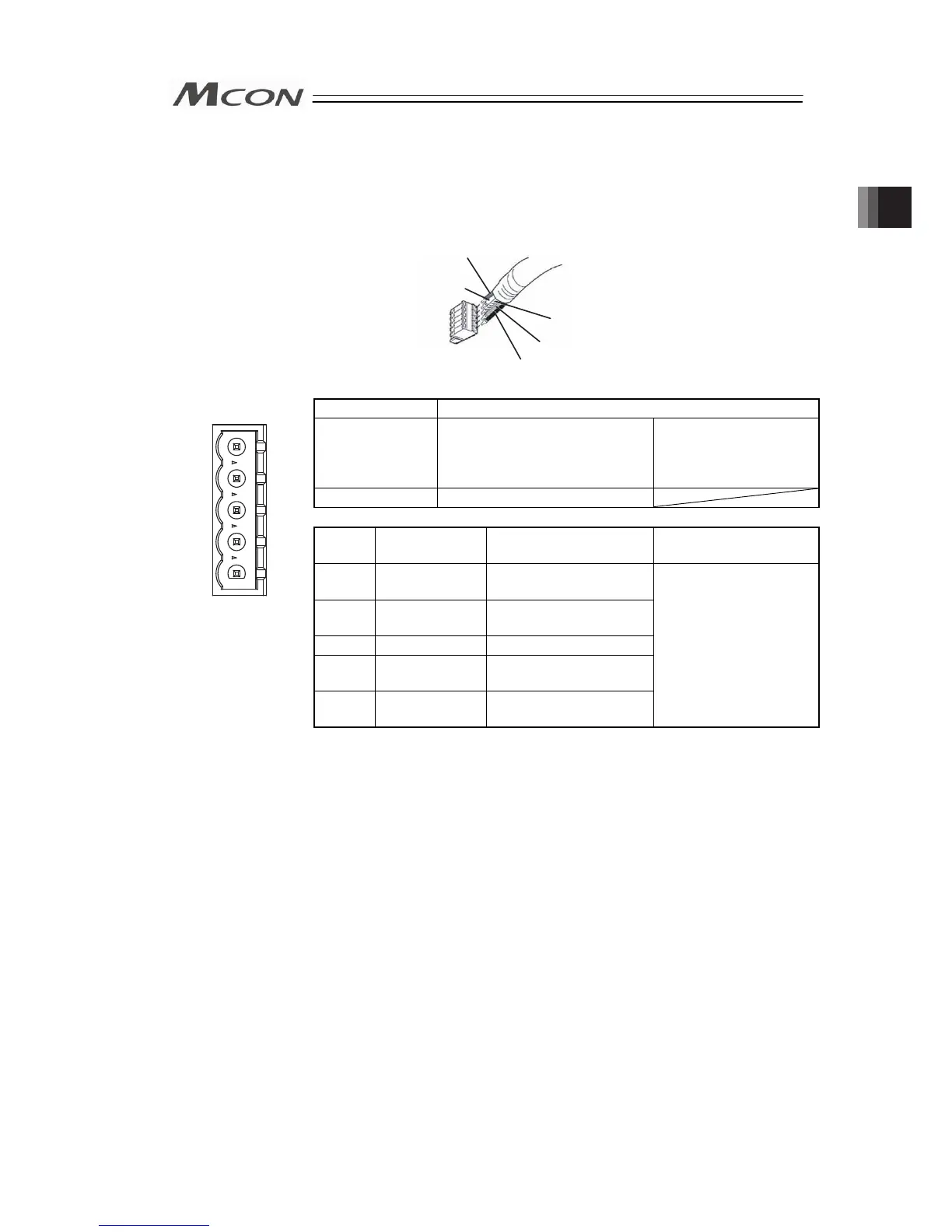
2.3.8 Wiring Layout of Fieldbus Connector
Check the instruction manuals for each Fieldbus master unit and mounted PLC for the details.
1) DeviceNet Type
Shield
BL (CAN L)
RD (V+)
WT (CAN H)
BK (V
-
)
Connector Name DeviceNet Connector
Cable Side MSTB2.5/5-STF-5.08 AU M Enclosed in standard
package
Manufactured by
PHOENIX CONTACT
Controller Side MSTB2.5/5-GF-5.08 AU
Pin No.
Signal Name
(Color)
Description
Applicable cable
diameter
1
2
3
4
5
1 V- (BK)
Power Supply Cable
Negative Side
Front view of connector
on controller side
2 CAN L (BL)
Communication Data
Low Side
3 Shield (None) Shield
4 CAN H (WT)
Communication Data
High Side
5 V+ (RD)
Power Supply Cable
Positive Side
Dedicated cable for
DeviceNet
(Note) Connect a terminal resistor (121
Ω
) between CAN L and CAN H if the
unit comes to the end of the network. [Refer to 2.2 [7] Wiring Layout
for Fieldbus.]
Chapter 2 Wiring