58
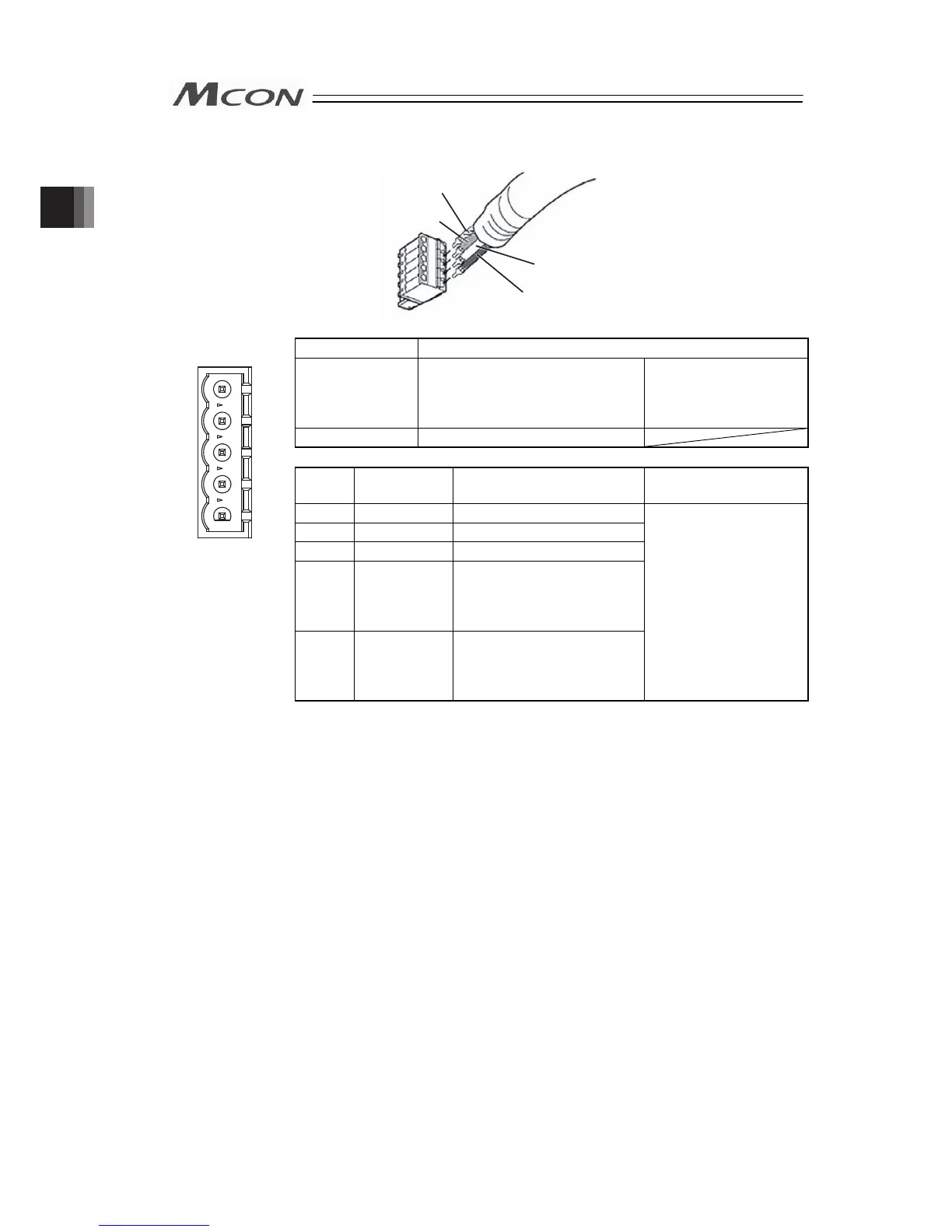
2) CC-Link Type
WT (DB)
BL (DA)
Shield (SLD)
YW (DG)
Connector Name CC-Link Connector
Cable Side MSTB2.5/5-STF-5.08 AU
Enclosed in standard
package
Manufactured by
PHOENIX CONTACT
Controller Side MSTB2.5/5-GF-5.08 AU
Pin No.
Signal Name
(Color)
Description
Applicable cable
diameter
1 DA (BL) Communication Line A
1
2
3
4
5
2 DB (WT) Communication Line B
3 DG (YW) Digital GND
4
SLD Connect the shield of the
shielded cable (Connect the
FG of the 5 pins and
controller FG internally)
Front view of
connector on
controller side
5
FG Frame Ground
(Connect the SLD of the 4
pins and controller FG
internally)
Dedicated cable for
CC-Link
(Note) Connect a terminal resistor between DA and DB if the unit comes to the
end of the network. [Refer to 2.2 [7] Wiring Layout for Fieldbus.]
Chapter 2 Wiring