59
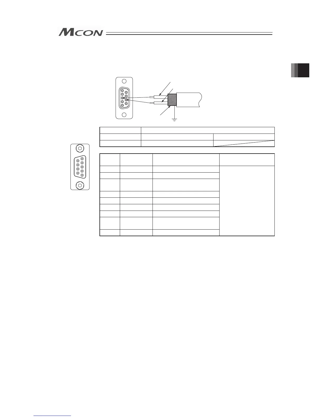
3) PROFIBUS-DP Type
5 1
9 6
Cable
Shield
Red B line (Positive side)
Use the type A cable for PROFIBUS-DP (EN5017).
Green A line (Negative side)
Connector Name PROFIBUS-DP Connector
Cable Side 9-pin D-sub Connector (Male) Please prepare separately
Controller Side 9-pin D-sub Connector (Female)
Pin No. Signal Name Description
Applicable cable
diameter
1 NC Disconnected
2 NC Disconnected
1
6
9
5
3
B-Line Communication Line B
(RS485)
4 RTS Request for Sending
5 GND Signal GND (Insulation)
Front view of
connector on
controller side
6 +5V +5V Output (Insulation)
7 NC Disconnected
8
A-Line Communication Line A
(RS485)
9 NC Disconnected
PROFIBUS-DP
Dedicated Cable
(Note) Connect a terminal resistor between A-line and B-line if the unit comes
to the end of the network. [Refer to 2.2 [7] Wiring Layout for Fieldbus.]
Chapter 2 Wiring

 Loading...


