48
2.3 Wiring Method
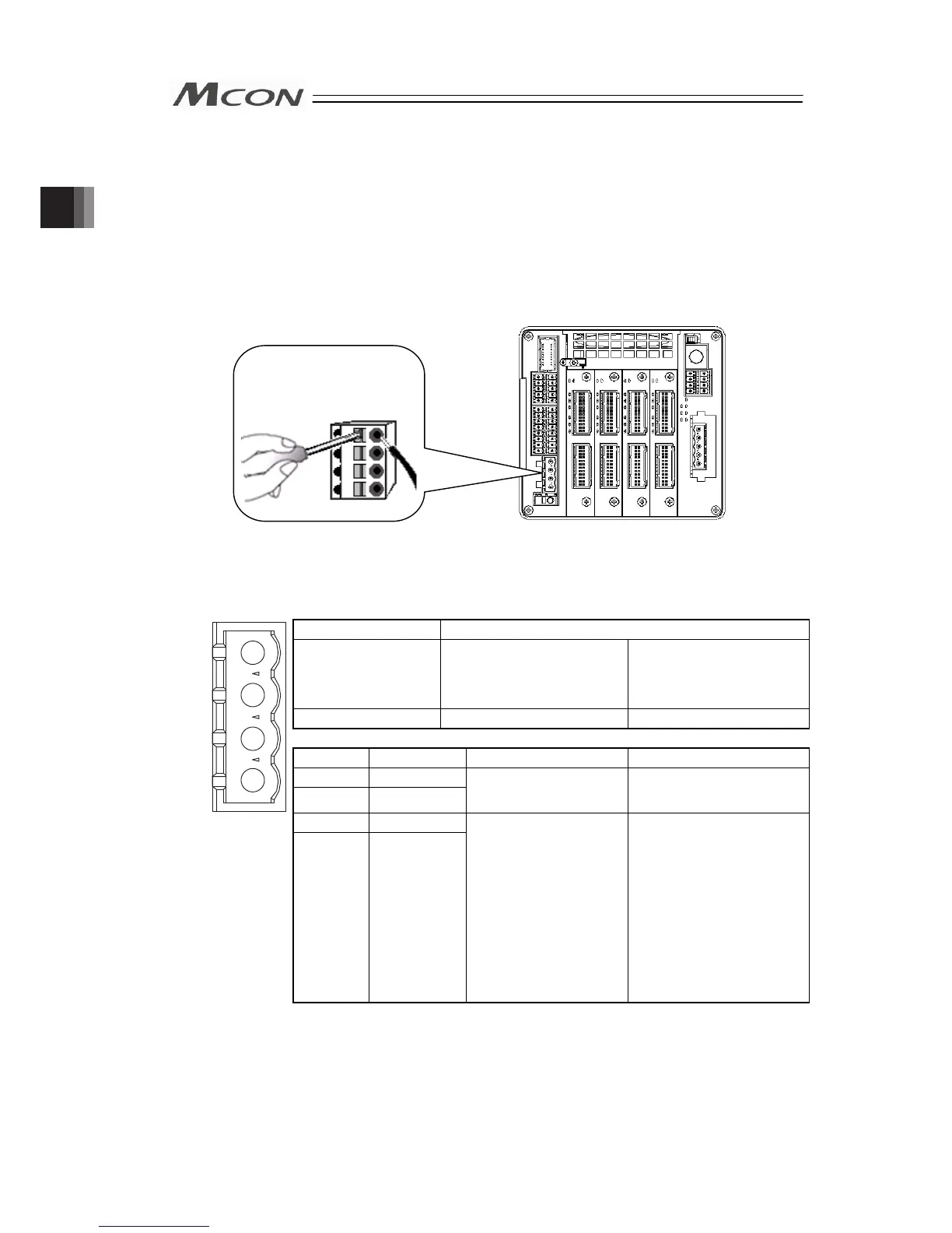
2.3.1 Connection to Power Input Connector
The wire of the power supply is to be connected to the enclosed connector (plug).
Strip the sheath of the applicable wires for 10mm and insert them to the connector. Push a
protrusion beside the cable inlet with a small slotted screwdriver to open the inlet. Once the
cable is inserted, take the slotted screwdriver OFF the protrusion to fix the cable to the terminal.
Connector Name Power Line Input Connector
Cable Side FKC2.5HC/4-ST-5.08 Enclosed in standard
package
Manufactured by
PHOENIX CONTACT
Controller Side MSTBA2.5HC/4-G-5.08
Pin No. Signal Name Description Applicable cable diameter
1 0V
1
2
3
4
2 CP+24V
Power Input for Control
(24V DC ±10%)
KIV0.5 to 0.3mm
2
(AWG20 to 22)
3 0V
Front view of
connector on
controller side
4 MP+24V
Power Input for Motor
Drive
(24V DC ±10%)
KIV3.5 to 0.75mm
2
(AWG12 to 18)
Select the cable thickness
allowable for the current
figured out in “1.3
Calculation for Power
Capacity”
(*)
.
* It is no problem to
calculate the current
consumption using the
rated value.
(Note) If supplying power with using a 24V DC, having it turned ON/OFF, keep the 0V
connected and have the +24V supplied/cut (cut one side only).
Accessory
Connector
(Plug)
Chapter 2 Wiring