51
2.3.4 Connecting with Actuator
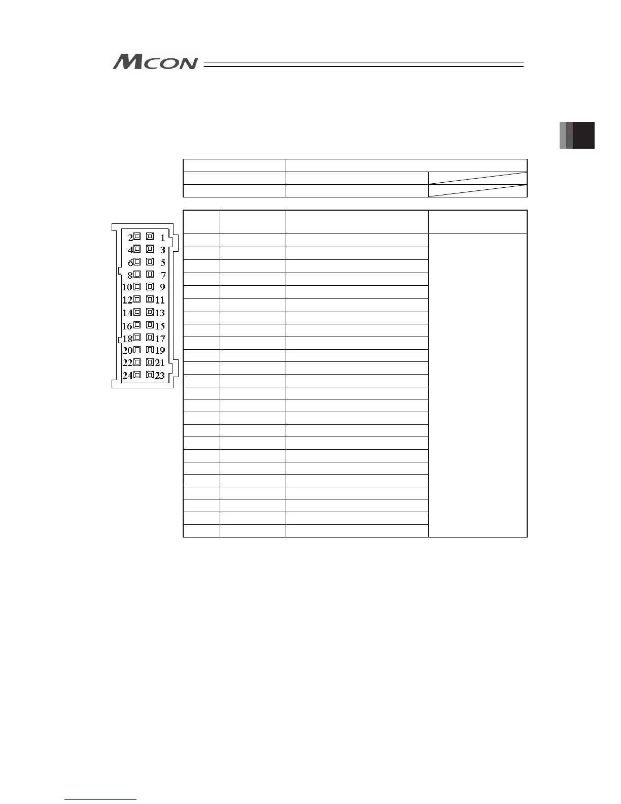
Connect the relay cables to the actuator connectors.
Check in the instruction manual of each actuator for the details of the relay cables.
Connector Name Actuator Connector
Cable Side PADP-24V-1-S
Controller Side S24B-PADSS-1
(1) Pulse Motor Type
Pin No. Signal Name Description
Applicable cable
diameter
1
φA
Motor Driving A-phase
2 VMM
Motor Power
3
φB
Motor Driving B-phase
4 VMM
Motor Power
5
φ/A
Motor Driving /A-phase
6
φ/B
Motor Driving /B-phase
7 LS+
Limit Switch Positive Side
8 LS-
Limit Switch Negative Side
9 BK+
Brake Release Positive Side
10 BK-
Brake Release Negative Side
11 NC
Not to be used
12 NC
Not to be used
13 A+
Encoder A-phase differential + input
14 A-
Encoder A-phase differential - input
15 B+
Encoder B-phase differential + input
16 B-
Encoder B-phase differential - input
17 5V
Encoder Power Supply
18 /PS
Encoder Line Driver Enable Output
19 GND
Ground
20 LSGND
Ground for Limit Switch
21 NC
Disconnected
22 NC
Disconnected
23 NC Disconnected
Front view of
connector on
controller side
24 FG
Grounding
Cable dedicated for
IAI products
Chapter 2 Wiring