13
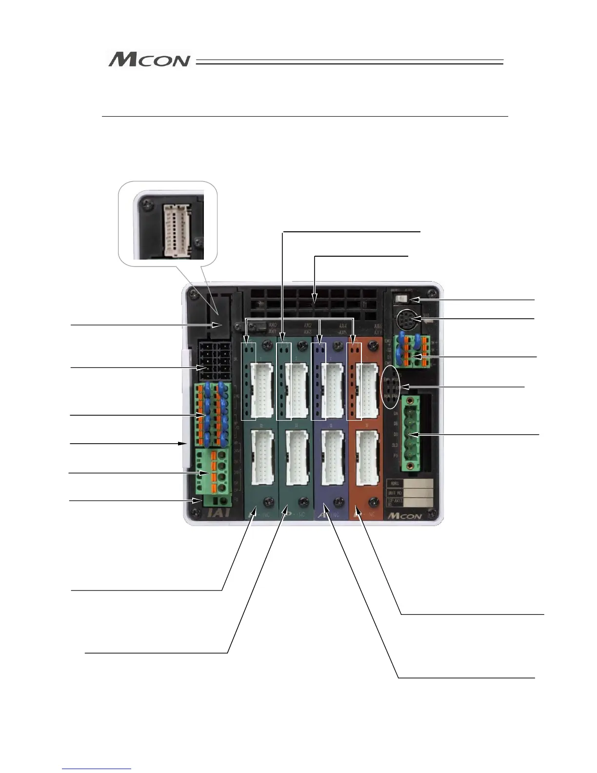
Name for Each Parts and Their Functions
zMCON-C/CG Type
6) Absolute Battery Connector
(for the simple absolute type)
9) Operation Mode
Setting Switch
10) SIO Connector
17) Slot 0
Actuator Connector
Upper side (1st axis) : Axis No.0 (AX0)
Lower side (2nd axis) : Axis No.1 (AX1)
7
2) Power Line Input
Connector
1) FG Terminal
3) Model Code Record
Card
11) System I/O
Connector
13) Fieldbus Connector
8) Fan Unit
16) Slot 1
Actuator Connector
Upper side (3rd axis) : Axis No.2 (AX2)
Lower side (4th axis) : Axis No.3 (AX3)
15) Slot 2
Actuator Connector
Upper side (5th axis) : Axis No.4 (AX4)
Lower side (6th axis) : Axis No.5 (AX5)
14) Slot 3
Actuator Connector
Upper side (7th axis) : Axis No.6 (AX6)
Lower side (8th axis) : Axis No.7 (AX7)
12) Status LED for
Fieldbus