14
1) FG Terminal
This is the terminal block for frame grounding. Since this controller is made of plastic, it is
necessary to ground from this terminal block. Have the grounding resistance kept at 100Ω
or less (Class D for grounding class (Grounding No. 3 in old standard)).
2) Power Line Input Connector
This is the connector to supply 24V DC power supply to the controller. The control power
supply and the motor power supply are to be input separately. This enables external drive
cutoff that cuts only the motor power supply. [Refer to 2.3.1]
3) Model Code Record Card
This is a card with information of the connected axes recorded on for eight axes at the
maximum. It is available to pull out from the controller and check the information. The serial
number of the controller is also recorded.
4) Drive Cutoff/Emergency Stop Input Connector
External drive cutoff and emergency stop can be performed individually for each slot (2
axes). [Refer to 2.3.3]
5) External Brake Input Connector
An external compulsory brake release can be performed on each axis. The brake is
ordinarily released with the servo ON and activated with the servo OFF. In the tuning at the
startup or in the maintenance work, have a brake release switch for each axis connected to
this connector to make a compulsory brake release available, and the actuator can be
moved manually while the servo is OFF. [Refer to 2.3.6]
6) Absolute Battery Connector
This connector is mounted on the simple absolute type. An external absolute battery box
for eight axes can be connected with one cable. This is not mounted on the incremental
type.
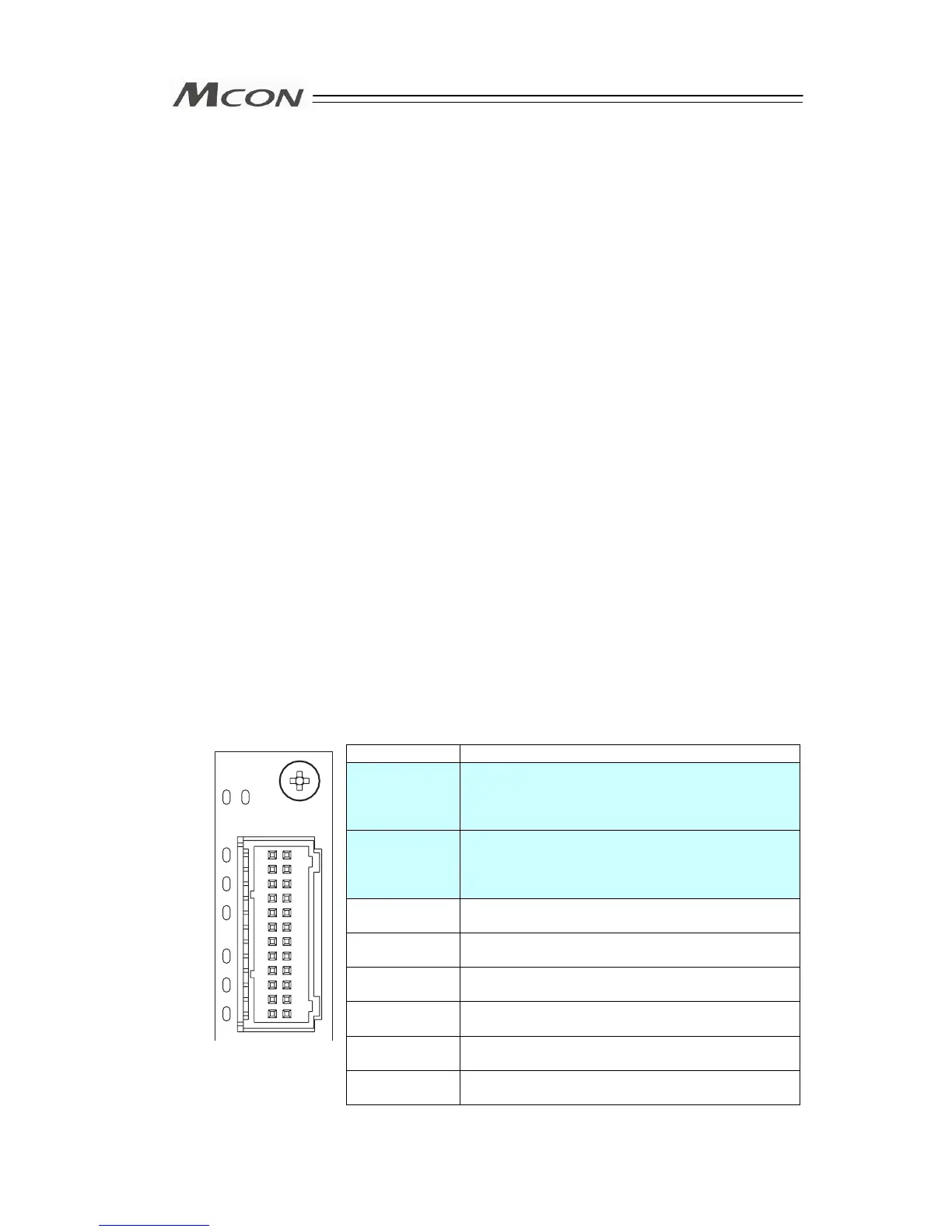
7) Status LEDs for Driver
These lamps indicate the status of the driver and that for absolute type for each slot (in 2
axes unit). There is no absolute status display for the incremental type.
Part Name Description
SYS I System status of driver for axis connected to
upper connector
(Servo ON: Green, Servo OFF: OFF,
Alarm generated, Emergency stop condition: Red)
SYS II System status of driver for axis connected to lower
connector
(Servo ON: Green, Servo OFF: OFF,
Alarm generated, Emergency stop condition: Red)
I–0 Absolute status of driver for axis connected to
upper connector 0
(Note 1)
I–1 Absolute status of driver for axis connected to
upper connector 1
(Note 1)
I–2 Absolute status of driver for axis connected to
upper connector 2
(Note 1)
II–0 Absolute status of driver for axis connected to
lower connector 0
(Note 1)
II–1 Absolute status of driver for axis connected to
lower connector 1
(Note 1)
II–2 Absolute status of driver for axis connected to
lower connector 2
(Note 1)
Note 1: Refer to “7.1 [1] Status LEDs for Driver” for details.
SYS
I II
2
1
0
2
1
0
I
II
 Loading...


