2. Wiring
125
[3] Wiring Method
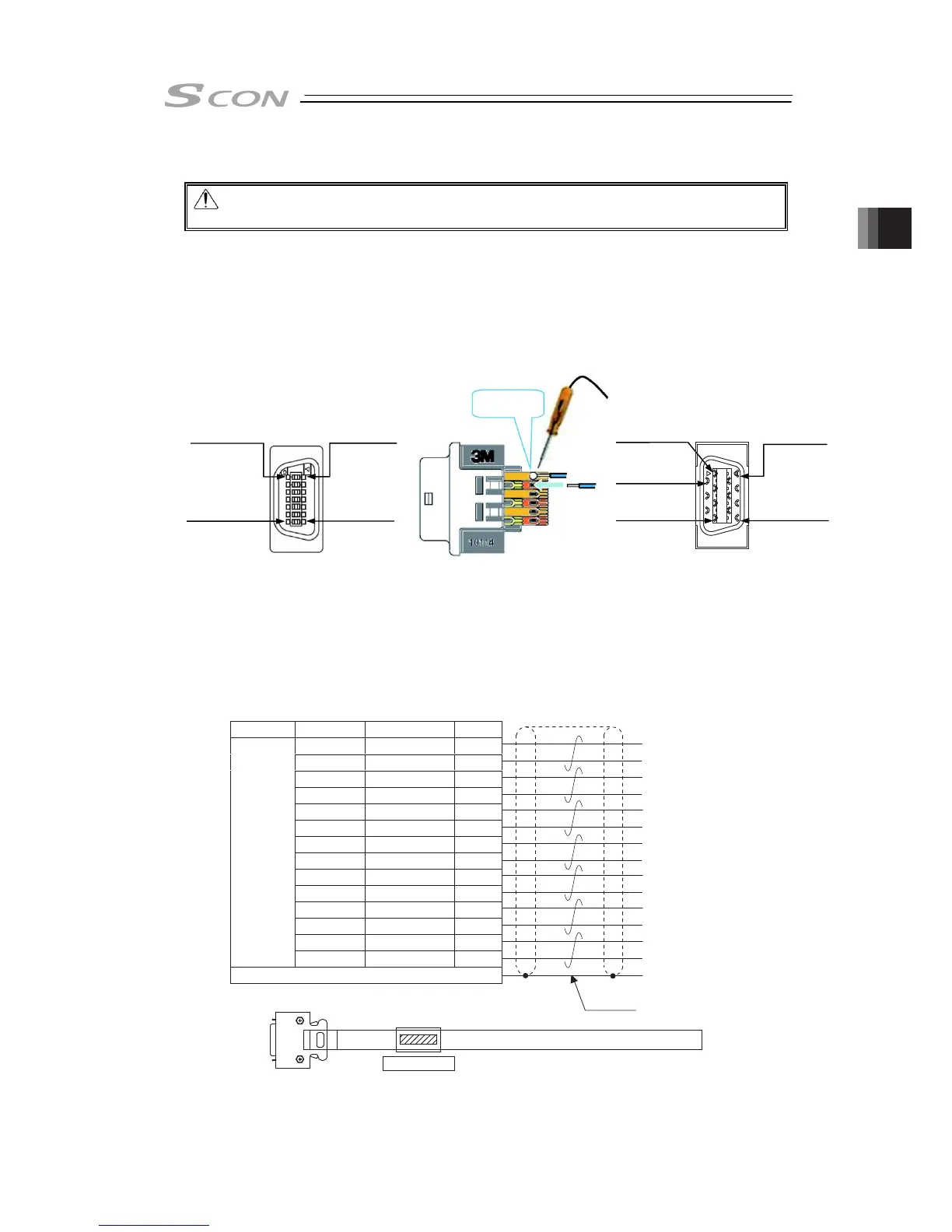
Connetct the multi-finction connector to the enclosed connector (Model: 10114-3000PE).
See below for how to lay out the power supply wires.
1) Prepare a cable.
(Multiple twisted pair shielded cable with AWG24 (0.2mm
2
) or cable enclosed in the
connected unit (host side)
2) Solder to the connector directly.
Pay attention not to have short circuit with a terminal next to it by having pretinning and so on.
[4] Connector with Cable (Option)
Model: CB-SC-PIOS□□□ □□□ is cable length: e.g. 020 = 2m
Cable length: For differential system, MAX. 10m
For open collector, MAX. 2m
(Note) There is no connector equipped on the host controller (PLC, etc.) side. Make an
appropriate treatment that suits the host controller (PLC, etc.). Also, to prevent
the noise influence as much as possible, make the cable as short as possible.
1
2
3
4
―
5
―
―
―
6
7
/AFB
AFB
SD+
SD-
8
BFB 9
/BFB 10
ZFB 11
/ZFB 12
GND 13
0.2mm
2
(AWG24)
GND 14
Wiring Color Signal Name No.
Shield is connected to the cable clamp
Host System Side
Shield
Black
White/Black
White/Red
White/Green
White/Yellow
White/Brown
White/Blue
White/Gray
Red
Green
Yellow
Brown
Blue
Gray
CB-SC-PIOS***
Caution: Enclosed only in plug and shell.
Do the same wiring layout as the following option.
2.5.6
1
st
Pin
7
th
Pin
8
th
Pin
14
th
Pin
1
st
Pin
8
th
Pin
7
th
Pin
14
th
Pin
2
nd
Pin
Solder

 Loading...


