2. Wiring
135
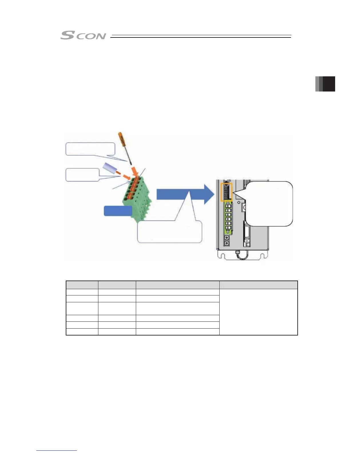
● Wiring Method
Connect the wiring of operation stop (system I/O connector) to the enclosed connector (Model
code: FMC1.5/6-ST-3.5: Phoenix Contact).
See below for how to lay out the power supply wires.
1) Push in such as a slotted screwdriver to open up the inlet.
2) Reveal the sheath for 7mm on the cable that satisfies the cable diameter complies the
specification shown in the table below and put it in the inlet.
3) Remove the slotted screwdriver from the protruded area. The inlet closes and affixes the
wire.
4) Connect all the wires in the same manner and insert the enclosed connector to the power
connector.
Enclosed Part
Pin Number and
Signal Name
1) Push in a slotted screwdriver
to the protruded area
3) Plug in the enclosed connector to
the power connector on the
controller side
2) Insert wire
Protruded Area
Wire Inlet
1. S1
2. S2
3. EMG+
4. EMG-
5. SDN1
6. SDN2
System I/O connector
Pin No. Signal name Items Applicable cable diameter
1 S1 Operation stop switch contact
2 S2 Operation stop switch contact
3 EMG+
Operation stop dedicated power
output
4 EMG- Operation stop input
5 SDN1 Drive cutoff contact output
6 SDN2 Drive cutoff contact output
1.25 to 0.5mm
2
(AWG16 to 20)
2.6.2

 Loading...


