3. Operation
151
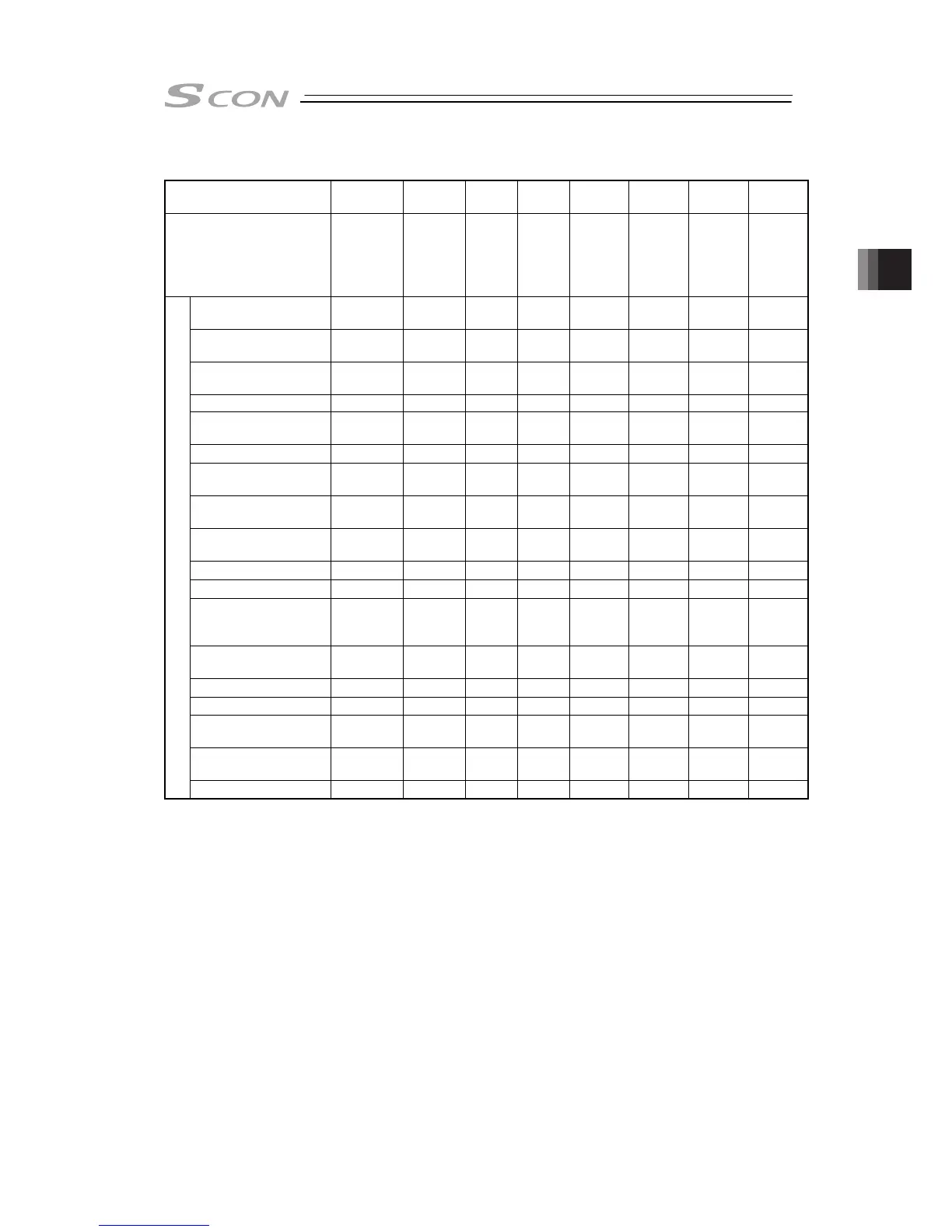
[1] PIO Pattern Selection and Main Functions
PIO Pattern
(Parameter No.25)
0 1 2 3 4 5 6 7
Mode
Positioning
mode
Teaching
mode
256-
point
mode
512-
point
mode
Solenoid
valve
mode 1
Solenoid
valve
mode 2
Pressing
operation
using
force
sensor
mode 1
Pressing
operation
using
force
sensor
mode 2
Number of positioning
points
64 64 256 512 7 3 32 5
Operation with the
Position No. Input
{ { { {
× ×
{
×
Position No. direct
command operation
× × × ×
{ {
×
{
Positioning
{ { { { { { { {
Velocity change during
the movement
{ { { {
× ×
{
×
Pressing (tension)
{ { { { {
× Δ
*2
Δ
*2
Pressing in use of
force sensor
× × × × × ×
{ {
Pitch Feeding
(relative moving feed)
{ { { { {
×
{ {
Home return signal
input
{ { { { {
×
{ {
Pause
{ { { { {
Δ
*1
{ {
Jog moving signal
×
{
× × × × × ×
Teaching signal input
(Current Position
Writing)
×
{
× × × × × ×
Brake release signal
input
{
×
{ { { { { {
Moving Signal Output
{ {
× × × × × ×
Zone signal output
{ { {
×
{ { { {
Position zone signal
output
{ { {
×
{ { { {
Position detection
feedback pulse output
{ { { { { { { {
Major functions
Vibration Control
{ { { { { { { {
*1 The pause signal is not provided. Refer to 3.2.4 [8].
*2 Tensile operation is not allowed.
(Reference)
Zone signal output signal : Set the zone range in parameter No.1 and 2. The signal is always
effective after home return is completed.
Position zone signal : This feature is associated with the specified position number. The zone
range is set in the position table. The zone range is enabled only when
the position is specified but disabled if another position is specified.
{: Valid function
3.2

 Loading...


