18
11) Multi-Function Connector (MF I/F) [Refer to 2.2.3 [7] Multi-function Connector]
It is a connector to use the feedback pulse output, analog output of loadcell load data and SIO
communication function (SIO2).
12) PIO Connector (PIO) [Refer to 2.6.4 Connection of PIO]
The PIO connector is used for control I/O signals.
(Note) It is not mounted in fieldbus type.
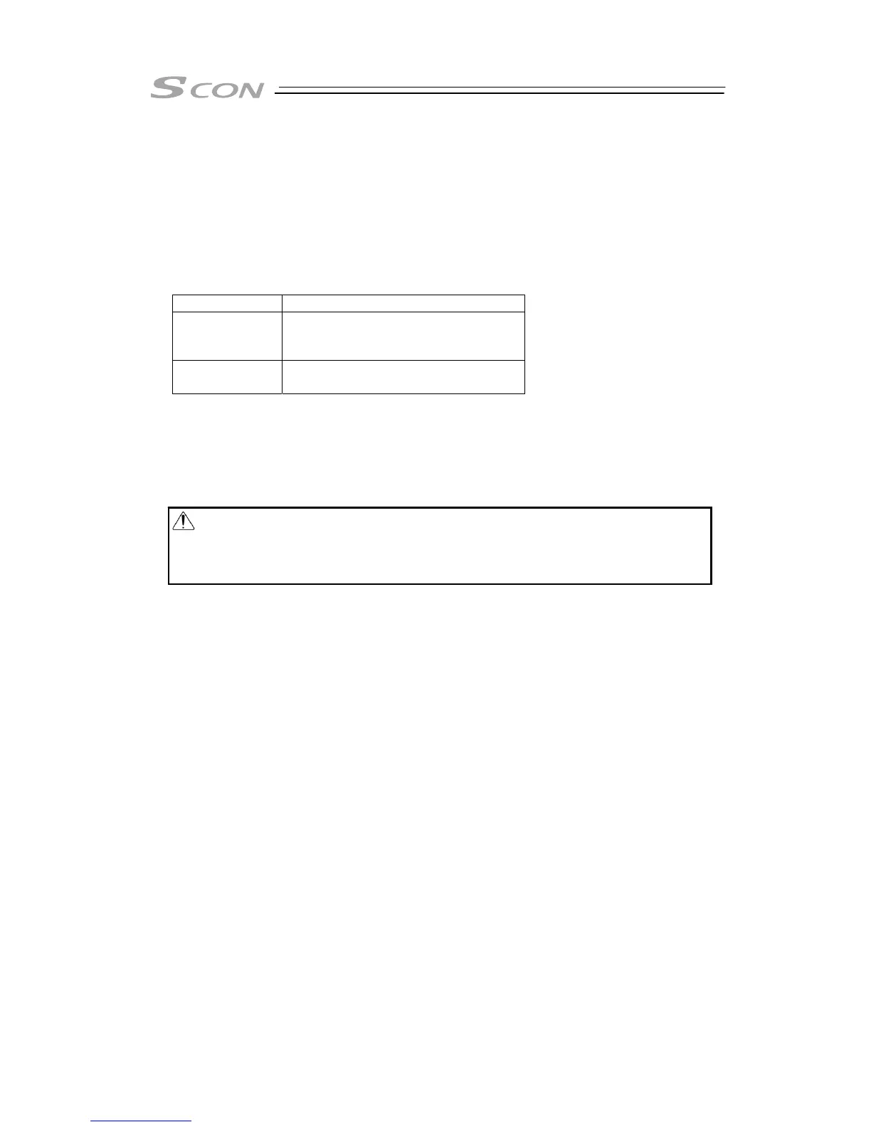
13) Operation Mode Setting Switch (MANU/AUTO)
The switch for interlock.
Setting to switch Available Operation
AUTO
Allows auto operation by PIO signals.
The teaching tool can only operate the
monitor.
MANU
It is available to make manual
operations from a teaching tool.
14) SIO Connector (SIO) [Refer to 2.6.7 SIO Connector Connection]
The SIO connector is used to connect the controller with a teaching tool as PC software through
a proper communication cable.
15) Brake Release Switch (BK RLS/NOM)
For the actuator equipped with a brake, the switch is used to release the brake control.
16) Motor Power Supply Connector (BK PWR) [2.2.3 [2] Brake Power Supply Circuit]
For the actuator equipped with a brake, the connector supplies the power (24V DC) to release
the brake.
17) Encoder Connector (PG) [Refer to 2.2.3 [4] Motor • Encoder Circuit]
This connector is used to connect the encoder cable of the actuator.
18) Absolute Battery Connector
In the absolute specification, the connector is connected with the absolute battery.
19) Absolute Battery Holder (enclosed in the absolute specification)
This is the holder of the absolute battery.
Warning: Always set the switch to NOM in normal operation.
The brake would not work even with the servo OFF condition if the switch is
on the RLS side. In the vertical oriented mount, the work may drop and
cause an injury or the work to be damaged.

 Loading...


