20
●Operation Pattern (Assignment)
1) The operation pattern is to be set in Parameter No. 84 “Fieldbus Operation Mode”.
Parameter
No.84
Setting
Operation Pattern
Parameter
No.84
Setting
Operation Pattern
0 Remote I/O mode* 5 Posiiton/Simple Direct Mode 2
1 Posiiton/Simple Direct Mode 6 Half Direct Mode 2
2 Half Direct Mode 7 Remote I/O mode 3*
3 Full Direct Mode 8 Half Direct Mode 3
4 Remote I/O mode 2*
* Set the PIO pattern in Parameter No. 25 (refer to 2.1.2) at the same time.
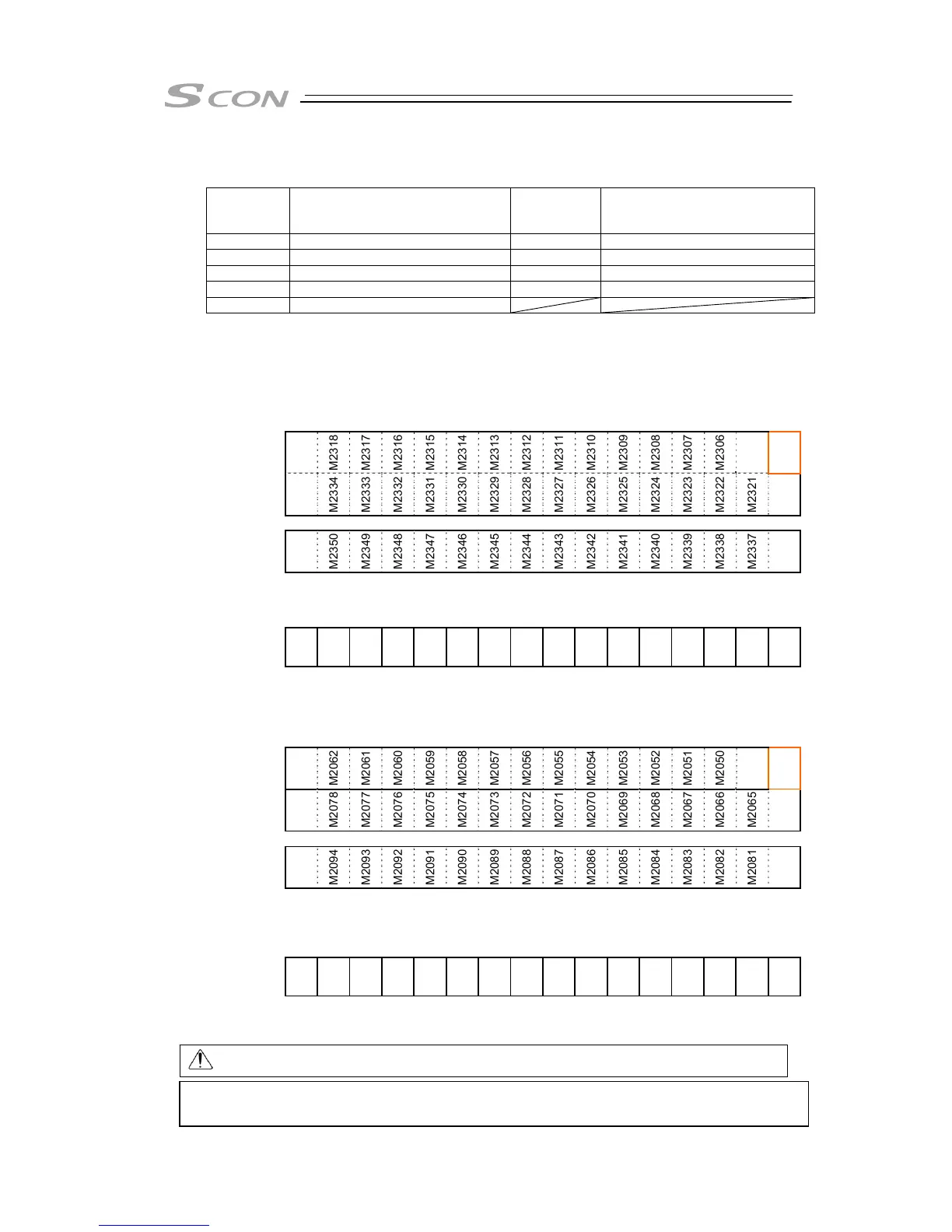
The set operation patterns are assigned to the internal relay (input signals to M2048 to 2303,
output signals to M2304 to M2559). Figure below shows an example for Position/Simple
Direct Mode (occupied 8 bytes).
☆
Example of SCON input side Assignment
b15 b14 b13 b12 b11 b10 b9 b8 b7 b6 b5 b4 b3 b2 b1 b0
Current
Position
(Lower)
M2319
M2318
M2317
M2316
M2315
M2314
M2313
M2312
M2311
M2310
M2309
M2308
M2307
M2306
M2305
M2304
Current
Position
(Upper)
M2335
M2334
M2333
M2332
M2331
M2330
M2329
M2328
M2327
M2326
M2325
M2324
M2323
M2322
M2321
M2320
b15 b14 b13 b12 b11 b10 b9 b8 b7 b6 b5 b4 b3 b2 b1 b0
Complete
Position
Number
M2351
M2350
M2349
M2348
M2347
M2346
M2345
M2344
M2343
M2342
M2341
M2340
M2339
M2338
M2337
M2336
Signal Name
of Complete
Position
Number
PM512
PM256
PM128
PM64
PM32
PM16
PM8
PM4
PM2
PM1
Status Signal
M2367
M2366
M2365
M2364
M2363
M2362
M2361
M2360
M2359
M2358
M2357
M2356
M2355
M2354
M2353
M2352
Status Signal
Name
EMGS
PWR
ZONE2
ZONE1
PZONE
MODES
WEND
RMDS
BALM
-
PSFL
SV
ALM
MOVE
HEND
PEND
☆
Example of SCON output side Assignment
b15 b14 b13 b12 b11 b10 b9 b8 b7 b6 b5 b4 b3 b2 b1 b0
Target
Position
(Lower)
M2063
M2062
M2061
M2060
M2059
M2058
M2057
M2056
M2055
M2054
M2053
M2052
M2051
M2050
M2049
M2048
Target
Position
(Upper)
M2079
M2078
M2077
M2076
M2075
M2074
M2073
M2072
M2071
M2070
M2069
M2068
M2067
M2066
M2065
M2064
b15 b14 b13 b12 b11 b10 b9 b8 b7 b6 b5 b4 b3 b2 b1 b0
Indicated
Position
Number
M2095
M2094
M2093
M2092
M2091
M2090
M2089
M2088
M2087
M2086
M2085
M2084
M2083
M2082
M2081
M2080
Signal Name
of Indicated
Position
Number
-
-
-
-
-
-
PC512
PC256
PC128
PC64
PC32
PC16
PC8
PC4
PC2
PC1
b15 b14 b13 b12 b11 b10 b9 b8 b7 b6 b5 b4 b3 b2 b1 b0
Control Signal
M2111
M2110
M2109
M2108
M2107
M2106
M2105
M2104
M2103
M2102
M2101
M2100
M2099
M2098
M2097
M2096
Control Signal
Name
BKRL
RMOD
-
-
PMOD
MODE
PWRT
JOG+
JOG-
JVEL
JISL
SON
RES
STP
HOME
CSTR
Caution: It is not applicable for pulse train control.
Understand the features of SCON with this manual before creating a ladder program.
[Refer to ME0329 LC Ladder Programming manual]

 Loading...


