10. Appendix
377
[12] Commanded Position No. Output Circuit
Depending on the result of the ready circuit, this circuit converts position No. to the binary code
and outputs the data from PLC to SCON.
156
OUT8
PC1
Command Position 1
AUX18
Position 1
Set
AUX20
Position 3
Set
AUX20
Position 3
Set
159
OUT9
PC2
Command Position 2
AUX19
Position 3
Set
[Position No.1]
[Position No.2]
[Position No.3]
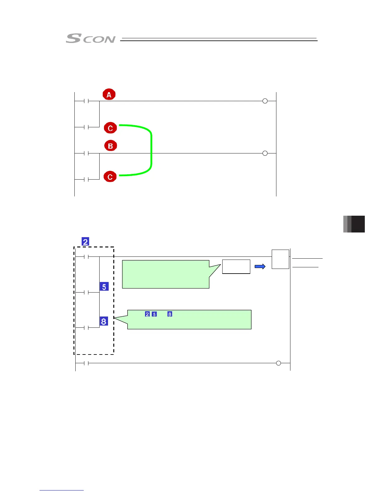
[13] Start Signal Output Circuit
After 20msec from the output of position No., this circuit outputs the start signal from PLC to
SCON.
162
166
AUX9
Auxiliary
Position 1
Positioning
Start
AUX12
Auxiliary
Position 2
Positioning
Start
AUX15
Auxiliary
Position 3
Positioning
Start
OUT13
CSTR
Waiting for start
Start
<Timer 5 (bit)>
a 1 16
Waiting for Start
TIM5
200ms
is set to
TIM5
20msec
Set this signal to be 2 to 4 times as
long as PLC scanning time so that it
is turned ON after position No. is output
securely. (The SCON input condition is
defined to turn the signal ON after 6msec.)
Each of 2 , 5 , and 8 signals is turned OFF if the actuator is
started by start signal. It is because PEND it turned OFF to turn
the moving circuit, a main circuit, ON. (Handshake)

 Loading...


