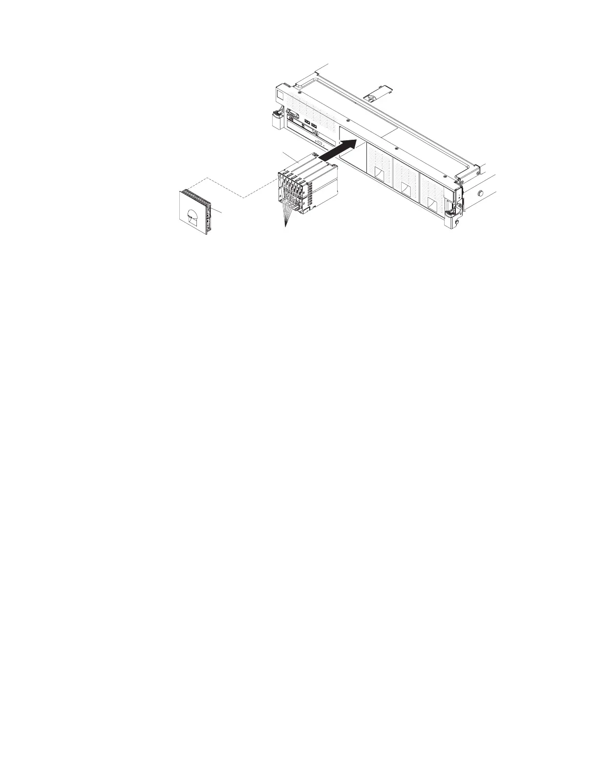
1.8-inch
filler panel
8x 1.8-inch
drive backplane
assembly
Drive LEDs
10. Slide the backplane assembly into the backplane bay until it clicks into place.
11. Connect the combination power/configuration cable end to the power and
configuration connectors on the backplane assembly; then, connect the power
connector on the other end of the cable to the backplane power connector on
the system board. See the following cabling illustration.
Note: You can connect the cables to the backplane before you install the
backplane onto the cage or you can connect the cables after you install the
backplane, if that is easier for you.
114 System x3750 M4 Types 8722 and 8733: Installation and Service Guide
 Loading...


