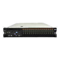
2. Align the cover over the server (toward the rear of the server) until the cover
edges slip into position over the chassis.
Cover release
latch
Top cover
3. Slide the cover toward the front of the server until the cover starts to engage on
the server; then, press down on the cover release latch until it clicks into place.
Connecting the cables
This information describes how to connect the server cables.
About this task
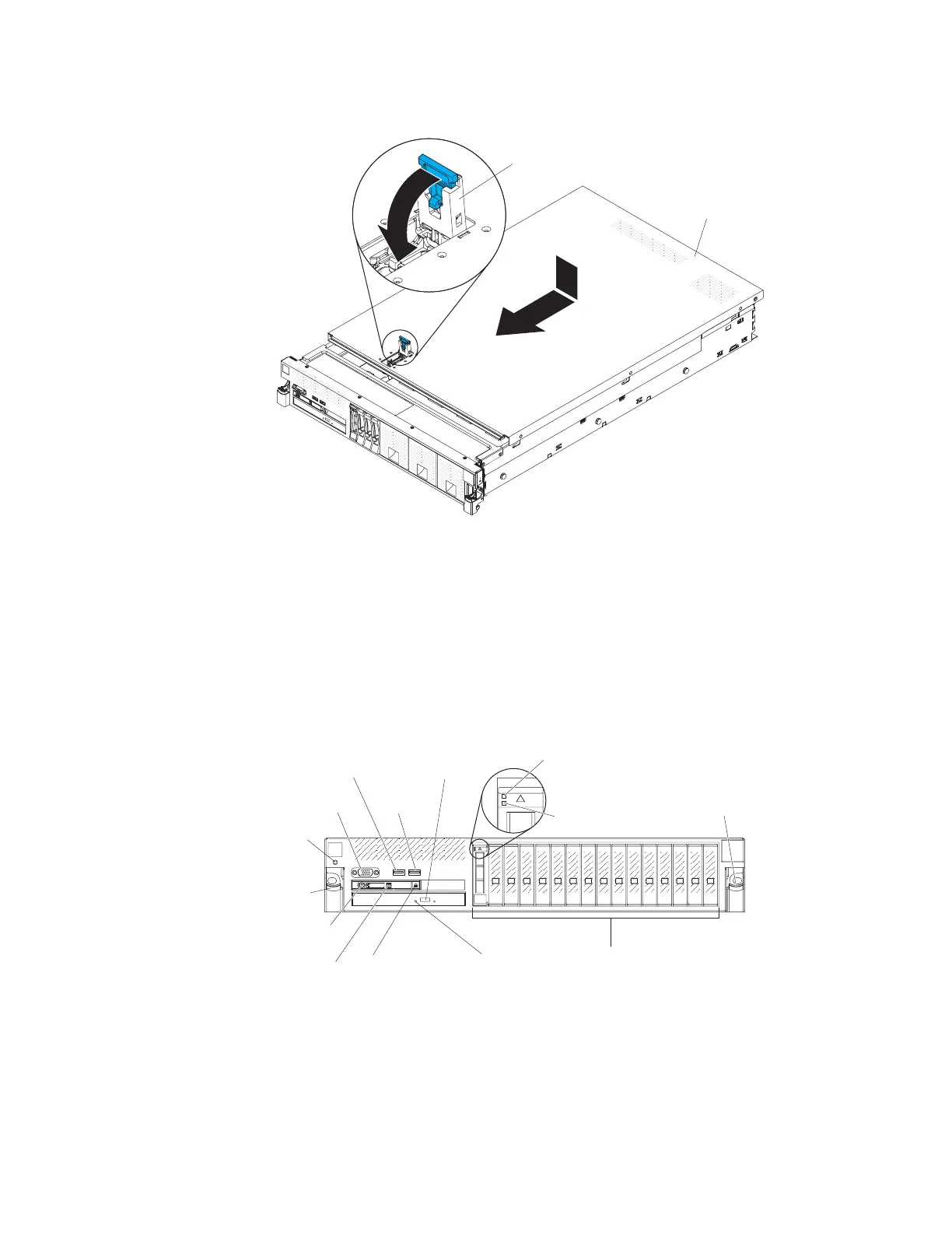
The following illustration shows the locations of the input and output connectors
on the front of the server.
Video
connector
USB 1
connector
USB 2
connector
0
12
3
4
56
7
8
910
11 12
13
14
15
Drive bays
Rack release
latch
Rack
release
latch
Power-on
button/LED
Locator
button/LED
Operator
information
panel release
latch
CD/DVD drive
activity LED
CD/DVD drive
eject button
Drive activity
LED (green)
Drive status
LED (yellow)
Electrostatic-
discharge
connector
The following illustration shows the locations of the input and output connectors
on the rear of the server.
134 System x3750 M4 Types 8722 and 8733: Installation and Service Guide
 Loading...


