Table 15. Connecting the SAS cables to the drive backplanes (BP) based on the
configurations (continued)
Drive backplane BP 1 BP 2 BP 3 BP 4
8x1.8-inch drive
backplane
v Connect two
SAS cables
from BP 1 to
the two SAS
signal
connectors on
the system
board.
v Connect two
SAS cables
from BP 2 to
the connectors
on the PCIe
adapter.
v Connect two
SAS cables
from BP 3 to
the connectors
on the PCIe
adapter.
v Connect two
SAS cables
from BP 4 to
the connectors
on the PCIe
adapter.
Note: Follow this general rule for connecting the SAS signal cables to the drive backplanes
and adapters:
v Port 0 on the drive backplane to Port 0 on the adapter
v Port 1 on the drive backplane to Port 1 on the adapter
Installing 2.5-inch and 1.8-inch hot-swap drives
This information provides instructions for installing 2.5-inch and 1.8-inch hot-swap
drives.
About this task
To install a hot-swap SAS or SATA drive, complete the following steps. For
information about installing drives, see “Installing drives” on page 54.
Note: If you install only one drive, you must install it in drive bay 0.
Procedure
1. Read the safety information and installation guidelines, see “Safety” on page vii
and “Installation guidelines” on page 35.
2. Touch the static-protective package that contains the drive to any unpainted
metal surface on the server; then, remove the drive from the package and place
it on a static-protective surface.
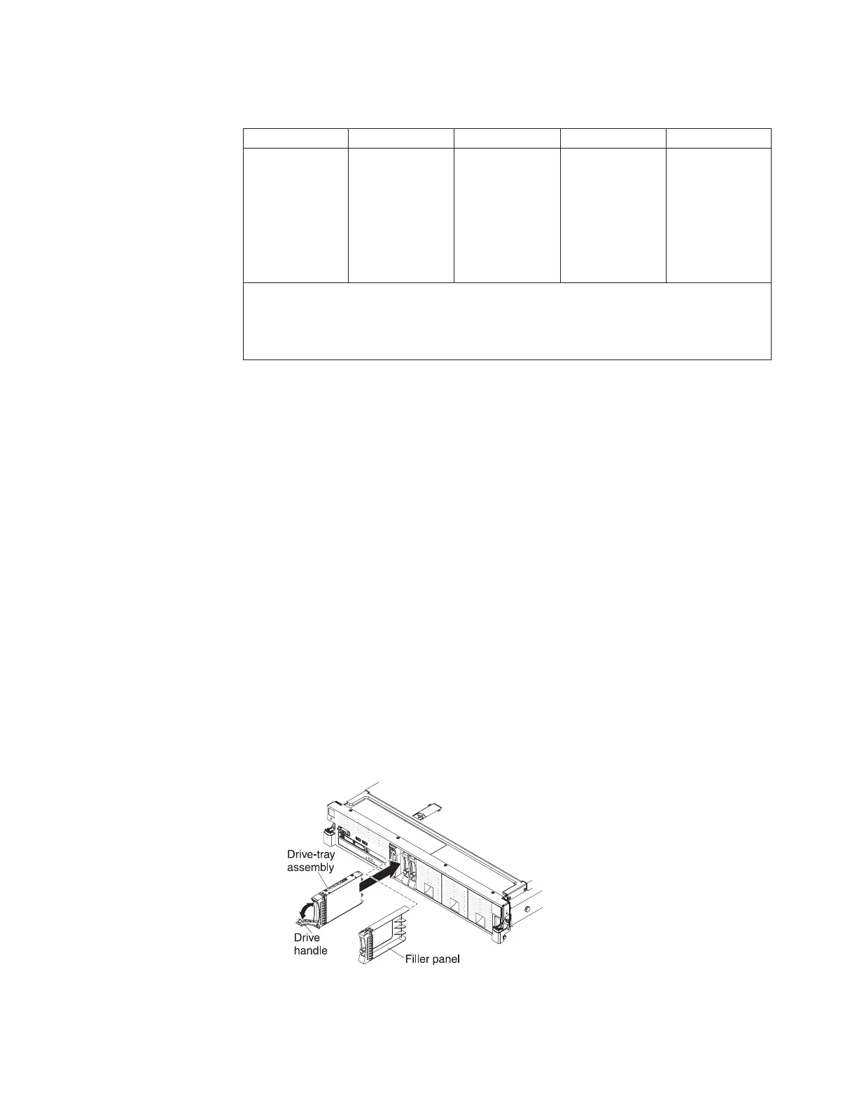
3. To install a 2.5-inch drive, complete the following steps:
a. Remove the filler panel from the empty drive bay.
b. Make sure that the drive-tray handle is in the open (unlocked) position.
c. Align the drive assembly with the guide rails in the bay.
d. Gently push the drive assembly into the drive bay until the drive stops.
e. Rotate the drive-tray handle to the closed (locked) position.
f. Skip to step 5.
Chapter 2. Installing optional devices 65
 Loading...


