Installing the 4x2.5-inch hot-swap drive backplane
This information provides instructions on how to install the 4x2.5-inch hot-swap
drive backplane.
About this task
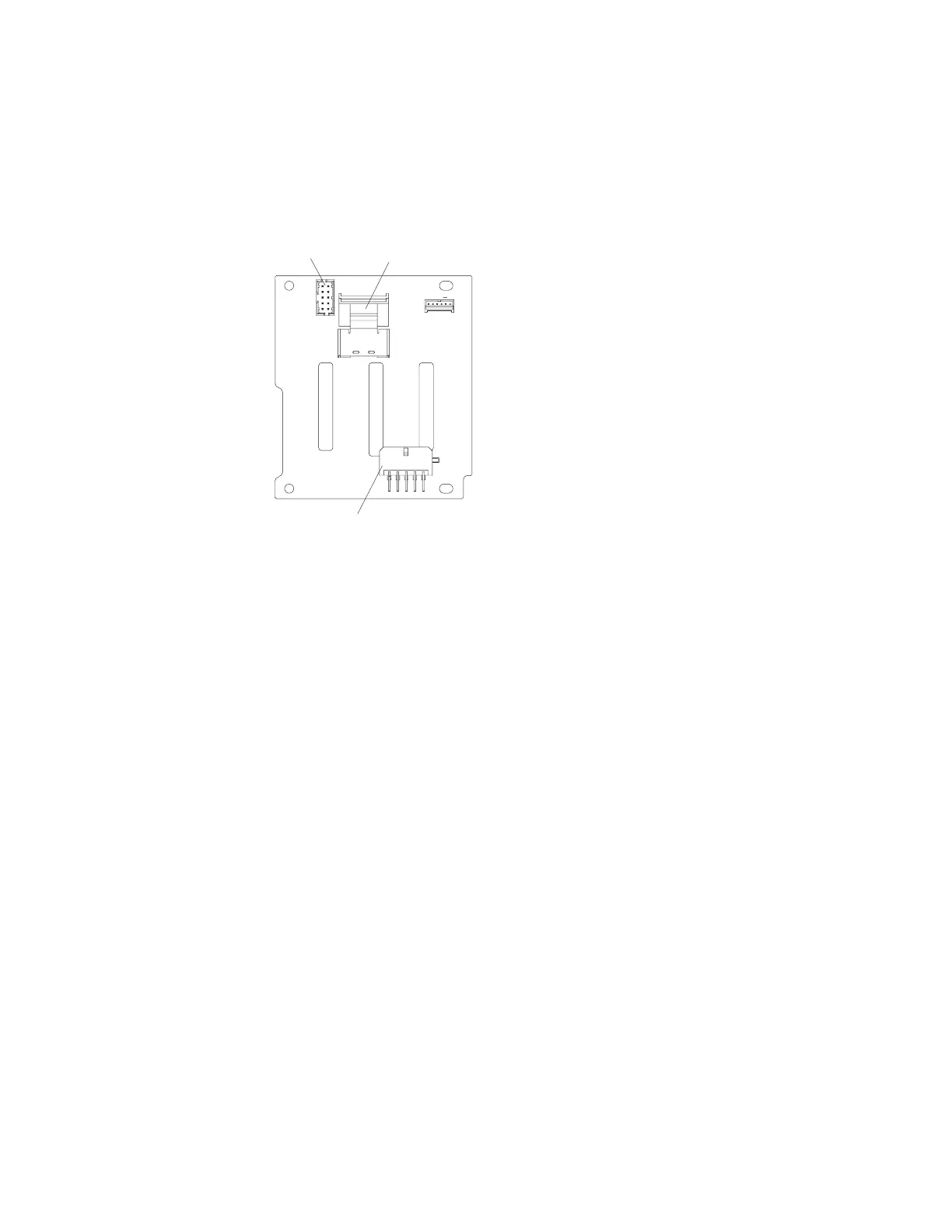
SAS signal
connector
SAS power
connector
Configuration
connector
:
Note:
v For more information about connecting the SAS signal cables to the drive
backplane, see “Connecting the SAS cables” on page 64).
v The right-angle SAS signal cables that come with the backplane only connect to
the SAS signal cable connectors on the system board.
To install the 4x2.5-inch hot-swap drive backplane, complete the following steps:
Procedure
1. Read the safety information and installation guidelines, see “Safety” on page
vii and “Installation guidelines” on page 35.
2. Turn off the server (see “Turning off the server” on page 22) and all attached
peripheral devices. Disconnect all power cords; then, disconnect all external
cables from the server.
3. Remove the top cover (see “Removing the server top cover” on page 38).
4. Remove the fan cage assembly (see “Removing the fan cage assembly” on
page 42).
5. Remove the microprocessor and memory expansion tray (see “Removing the
microprocessor and memory expansion tray assembly” on page 305) or DIMM
air baffle (see “Removing the DIMM air baffle” on page 232), whichever one is
installed.
6. Open the SAS cable guide cover.
7. If backplane filler panels are installed in the backplane bay in which you are
installing the backplane, remove the backplane filler panels.
8. Connect the combination power/configuration cable end to the power and
configuration connectors on the drive backplane; then, connect the power
Chapter 2. Installing optional devices 125
 Loading...