v Remind button: This button places the system-error LED on the operator
information panel into Remind mode. In Remind mode, the system-error LED
flashes once every 2 seconds until the problem is corrected, the server is
restarted, or a new problem occurs.
By placing the system-error LED indicator in Remind mode, you acknowledge
that you are aware of the last failure but will not take immediate action to
correct the problem.
v Boot code display: This display provides boot error codes that indicates the
point at which the system stopped during the boot block and POST. A boot code
is a byte value that is produced by UEFI. In addition to UEFI codes, this display
provide error codes in the event of a microprocessor error or a power fault.
Along with the IMM event log, the error codes can provide suggested
components to be replaced.
v Reset button: Press this button to reset the server and run the power-on self-test
(POST). You might have to use a pen or the end of a straightened paper clip to
press the button. The Reset button is in the lower-right corner of the light path
diagnostics panel.
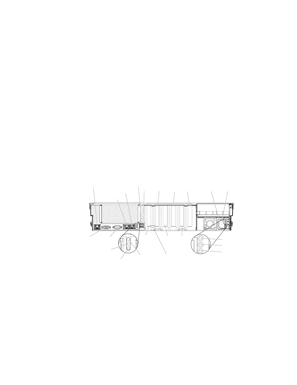
Rear view
This information provides a description of the controls, LEDs, and buttons on rear
of the server.
The following illustrations show the connectors and LEDs on the rear of the server.
Video
connector
Systems-management
Ethernet connector
(IMM2)
Serial
connector
Ethernet 1
Ethernet 2
USB 5
USB 6
Power-on
LED (green)
Locator
LED (blue)
System error
LED (amber)
10 Gb
Ethernet
adapter
slot
Slot 4,
PCIe
Gen 3
Slot 5,
PCIe
Gen 3
Slot 6,
PCIe
Gen 3
Slot 7,
PCIe
Gen 3
Slot 8,
PCIe
Gen 3
Power
supply 1
AC
DC
!
AC power LED (green)
DC power LED (green)
Power supply
error LED (amber)
NMI
button
Power
connector
v Systems-management Ethernet connector: Use this connector to manage the
server, by using a dedicated management network. If you use this connector, the
IMM cannot be accessed directly from the production network. A dedicated
management network provides additional security by physically separating the
management network traffic from the production network. You can use the
Setup utility to configure the server to use a dedicated systems-management
network or a shared network.
v Video connector: Connect a monitor to this connector. The video connectors on
the front and rear of the server can be used simultaneously.
Note: The maximum video resolution is 1600 x 1200 at 75 Hz.
20 System x3750 M4 Types 8722 and 8733: Installation and Service Guide
 Loading...


