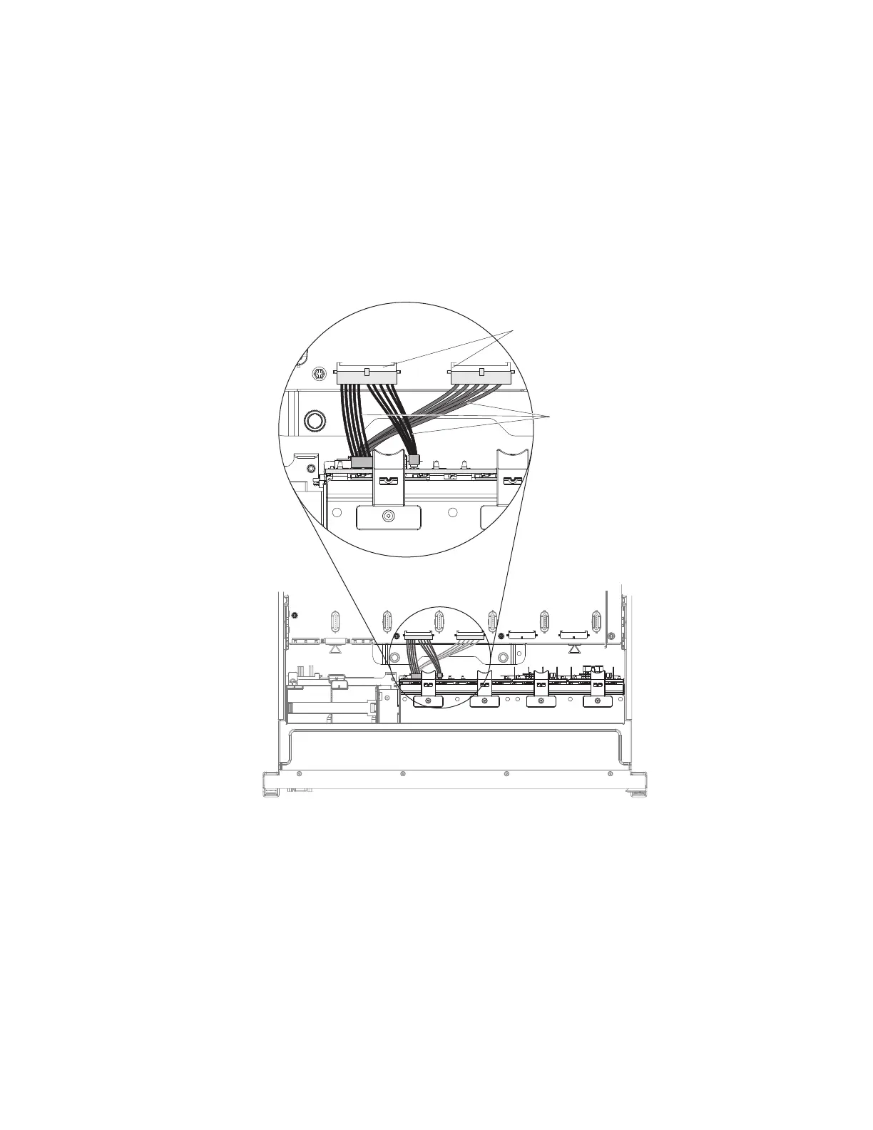
board. The power connector on the end of the black cable (which might be
labelled 1/3) connects to backplane connector 1 or 3 on the system board. The
power connector on the end of the gray cable (which might be labelled 2/4)
connects to backplane connector 2 or 4 on the system board. Connect the
configuration connector on the combination power/configuration cable to the
configuration connector on the drive backplane. Connect the other power
connector on the combination power/configuration cable to the power
connector on the backplane.
Note: You can connect the cables to the backplane before you install the
backplane onto the cage, or you can connect the cables after you install the
backplane, if that is easier for you.
Backplane
power/
configuration
cable
1/3
2/4
Backplane
power
connectors
9. Insert the backplane tabs into the slots on the bottom of the backplane cage
and rotate the backplane assembly forward until the backplane locks in place.
118 System x3750 M4 Types 8722 and 8733: Installation and Service Guide
 Loading...


