3 - 3
Cygnus 2 Operating Manual
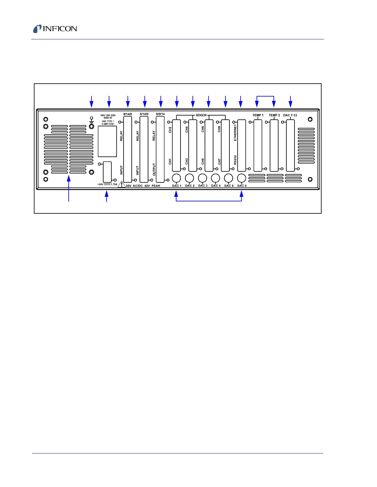
3.2 Rear Panel Interfaces
Interfaces for Cygnus 2 are located on the rear panel, see Figure 3-2.
Figure 3-2 Cygnus 2 rear panel
1 Ground Stud
Refer to section 2.2.2, Connections to Earth Ground, on page 2-5.
2 AC Power Inlet, Fuse and Mains Switch
Provides main power switch, fuse and common connector for international plug
sets.
3 8 Relay x 14 Input I/O Card (standard)
Provides pin connection for 8 Relays rated for 30 V (dc) or
30 V (ac) RMS or 42 V (peak) maximum, and 14 TTL inputs.
4 8 Relay x 14 Input I/O Card (optional)
Provides pin connection for 8 relays rated for 30 V (dc) or
30 V (ac) RMS or 42 V (peak) maximum, and 14 TTL inputs.
5 8 Relay x 14 Output I/O Card (optional)
Provides pin connection for 8 relays rated for 30 V (dc) or 30 V (ac) RMS or
42 V (peak) maximum, and 14 open collector type outputs.
6 Sensor Connectors - Channels 1 and 2 (standard)
Provides connection for two Sensor channels.
7 Sensor Connectors - Channels 3 and 4 (optional)
Expansion panel to accommodate the optional addition of two more sensors,
Sensors 3 and 4.
123 945678 10 11 12
151413