Intel® Server System M50CYP1UR Family System Integration and Service Guide
81
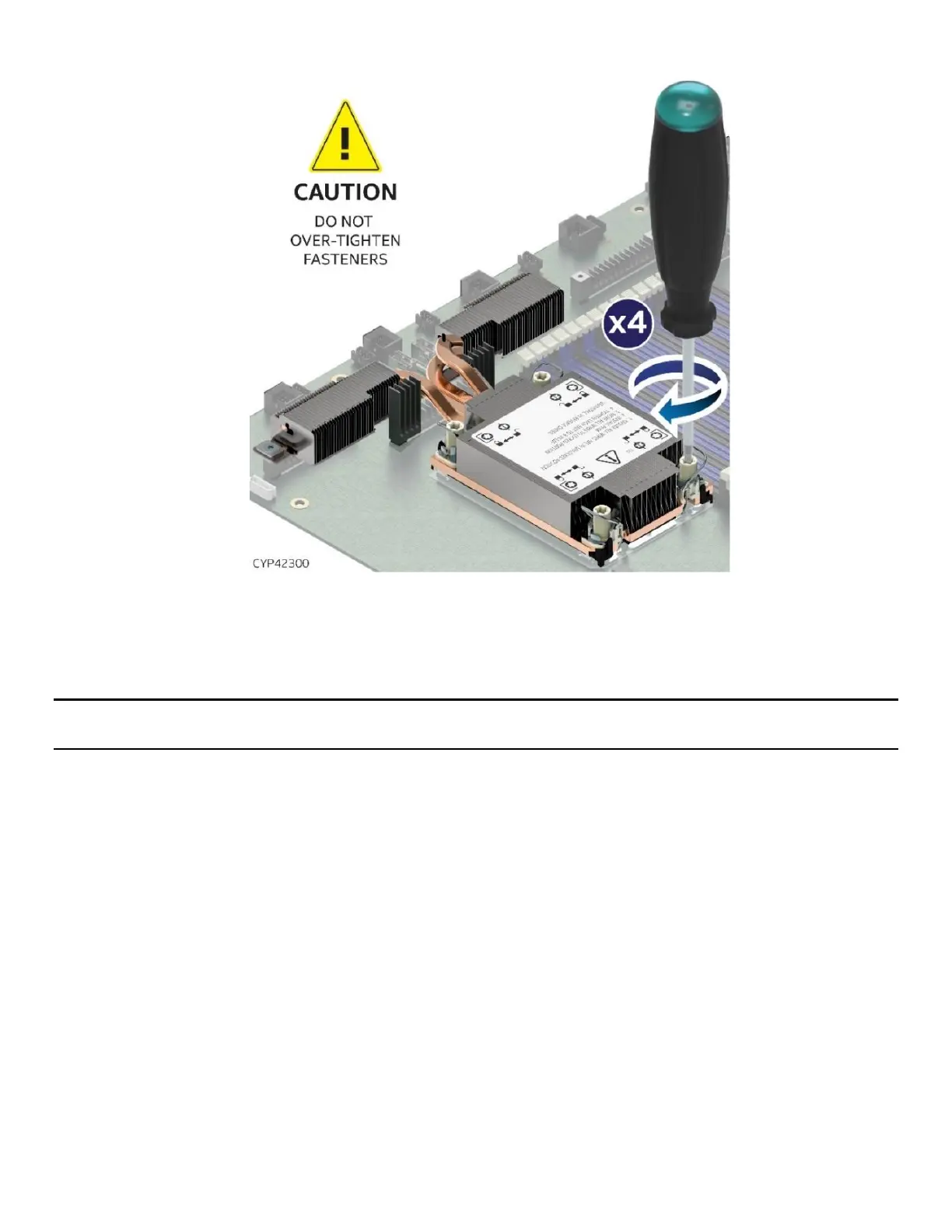
Figure 95. Tighten Heat Sink Extension Screws
8. Tighten the heat sink fasteners using a T30 Torx* screwdriver to 8 in-lb. No specific sequence is needed
for tightening.
9. Reinstall the system top cover (see Section 6.1.2).
Important: Do not install a processor heat sink on an empty socket. Also, only install a socket cover on an
empty socket.
6.6 2.5” SSD Drive Removal, Assembly, and Installation
The Intel® Server System M50CYP1UR family has front drive bay chassis options that support 2.5” form
factor drives (SSDs only). Additionally, 7 mm thick SSDs with a form factor of 2.5” are supported when used
in conjunction with the supplied drive blank for 2.5” bays. Each storage drive that interfaces with a backplane
is mounted to a tool-less, non-detachable, hot swap drive mounting rail.
This section provides instructions for drive removal from the chassis, drive installation into the chassis, and
drive assembly. Figure 96 identifies the drive bay components. For drive population rules, see the Intel®
Server System M50CYP1UR Family Technical Product Specification (TPS).
Required Tools and Supplies
• Anti-static wrist strap and conductive workbench pad (recommended)
The following figure identifies the 2.5” drive bay components.

 Loading...


