Intel® Server Board S1200BT Service Guide 7
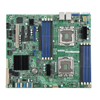
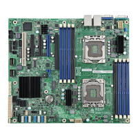
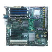
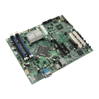
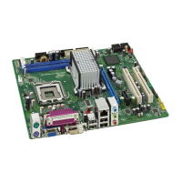
Figure 3. Connector and Component Location
A. Slot 1, 32 Mbit/33 MHz PCI R. System FAN2 and System FAN3
Connector
B. TPM S. CPU Connector
C. Slot 3/4, PCI Express* Gen2 x4 (x8
connector)
T. CPU Fan Connector
D. Slot 5, PCI Express* Gen2 x4 (x8
connector)
U. USB connector for smart module
E. Slot 6, PCI Express* Gen2 x8 (x16
connector) V SAS Module connector
V. SAS Module Connector
F. Chassis Intrusion W. IPMB
G. SATA_KEY X. SYS_FAN_1
H. Two Ethernet and Dual USB COMBO Y. HSBP
I. Video Port Z. SATA_SGPIO
J. External Serial port AA. Internal Serial Connector
K. RMM4 Lite Connector BB. Front Panel Connector
L. CPU Power Connector CC. HDD LED
M. SYS_FAN_4 DD. Internal USB Connector
N. RMM4 Dedicated NIC connector EE. CMOS Battery
O. Four DIMM Slots FF. Four 3Gb/s SATA ports
P. P/S AUX GG. Two 6Gb/s SATA ports
Q. MAIN POWER HH. Smart Module
 Loading...
