74 Intel® Server Board S1200BT Service Guide
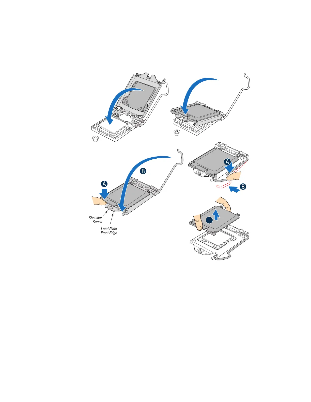
10. Close the load plate (see letter “A” in Figure 50), close the socket lever, and ensure
the load plate tab engages under the socket lever when fully closed (see letter “B”
and “C” in Figure 50).
Figure 50. Close the Load Plate and Socket Lever
Note: Make sure the alignment triangle mark and the alignment triangle cutout align correctly.
To assist in package orientation and alignment with the socket:
Installing the Heatsink(s)
1. If a protective film covers the thermal interface material (TIM) on the underside of
the heatsink, remove the protective film.
2. Align heatsink fins to the front and back of the chassis for correct airflow. Airflow
goes from front-to-back of chassis.
3. Each heatsink has four captive fasteners and should be tightened as shown.
AF004576
AF004579
AF004580
Save the
protective
cover.
A