12 Intel® Server Board S1200BT Service Guide
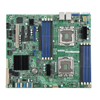
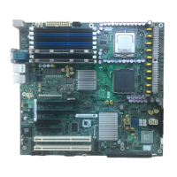
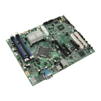
Figure 6. Configuration Jumpers Location
Back Panel Connectors
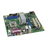
Figure 7. Back Panel Connectors
The NIC LEDs at the right and left of each NIC provide the following information.
J1E2: Protected RTC
(CMOS clear)
1-2 These pins should have a jumper in place for normal system
operation. (Default)
2-3 If these pins are jumpered, the CMOS settings are cleared on the
next reset.
Note: These pins should not be jumpered for normal operation.
J1F3: BIOS Recovery 1-2 These pins should have a jumper in place for normal system
operation.(Default)
2-3 The main system BIOS will not boot with these pins jumpered.
Note: The system will boot from EFI-bootable recovery media with a
recovery BIOS image.
J1F2: ME Force
Recovery
1-2 These pins should have a jumper in place for normal system
operation. (Default)
2-3 ME force update model
Jumper Name Pins What happens at system reset…
A. Serial Port A C. NIC Port 1 (1 Gb) and Dual USB Port
Connector
B. Video D. NIC Port 2 (1 Gb) and Dual USB Port
Connector
 Loading...
