Appendix B — EA20X Imager
ED40 Decode Board Integration Guide 93
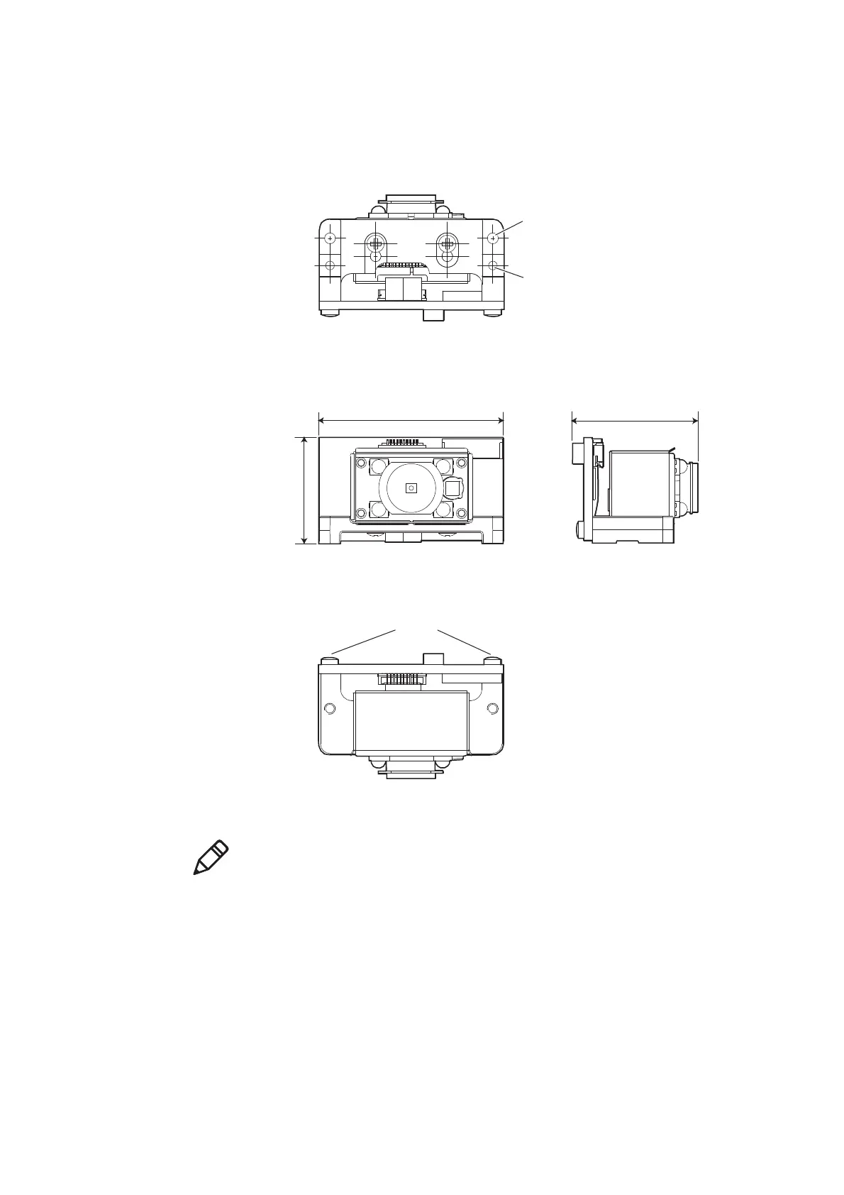
Mechanical Dimensions
The EA20X imager is mounted on the ED40 decode board using a mounting
bracket (available from Intermec).
EA20X + ED40 Mechanical Dimensions: Tolerances = ± 0.20 mm (0.008 in).
Positioning holes (2 places)
Mounting holes (2 places)
19.5 mm
0.77 in
34 mm
1.34 in
23.05 mm
0.91 in
M1.6 screws (2) to mount the PCB to bracket:
max torque 19 Ncm (1.68 lb-in) ± 1 Ncm (0.09 lb-in)
Imager Position 1
Positioning holes (2 places)
Mounting holes (2 places)
19.5 mm
0.77 in
34 mm
1.34 in
23.05 mm
0.91 in
M1.6 screws (2) to mount the PCB to bracket:
max torque 19 Ncm (1.68 lb-in) ± 1 Ncm (0.09 lb-in)
Imager Position 1
Note: As opposed to the other imagers, there is only one position for mounting
the EA20X. This is because the EA20X is slightly bigger than the other Intermec
imagers supported by the ED40 decode board.