Appendix D — EA30 Imager
138 ED40 Decode Board Integration Guide
25-Pin End Connected to the EA30 Imager: The 25-pin end of the ribbon cable is connected
to the imager.
Connecting the Ribbon Cable
Follow this procedure to connect the imager connector.
To connect the imager connector
1 Open the connector cover. Use the tip of your finger to open the cover in the
direction shown. Be careful not to force open the cover or open it more than
80° or it will break.
2 Pull gently on the ribbon cable along the axis of the cable, and remove the
ribbon cable.
3 Connect a new ribbon cable to the imager connector. Make sure that the
contacts are facing the board.
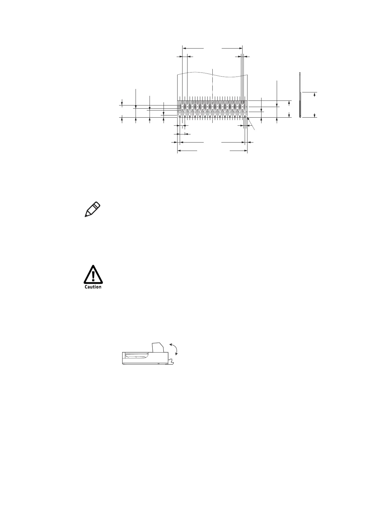
1.45
±0.1
1.05
±0.1
(0.3)
±0.07
0.85
±0.1
0.25
±0.1
0.3
±0.02
0.3
±0.07
0.6
±0.02
0.6
±0.02
B
±0.03
A
±0.03
(B+0.6)
±0.05
2-R0.2 MAX
3
2
±0.3
0.3
0.3
1.25
(Eective stacking
length)
0.65
T=0.12
±0.03
+0.04
-0.03
+0.04
-0.03
(Eective stacking
length)
(Reinforcement
board)
(Conductive plating)
Note: Intermec does have the capability to provide a 25-pin to 21-pin flex so that
the unitl can run off the same interface as EA11. Contact your OEM
representative for more information.
The connectors are very fragile. Open and close the connectors very
carefully.