Chapter 3 — Electrical Integration
ED40 Decode Board Integration Guide 15
USB Interface
The USB interface supports ISCP protocol for data output, imager control, and
configuration (raw data and encapsulated data modes supported).
These connections allow for normal operation and firmware download.
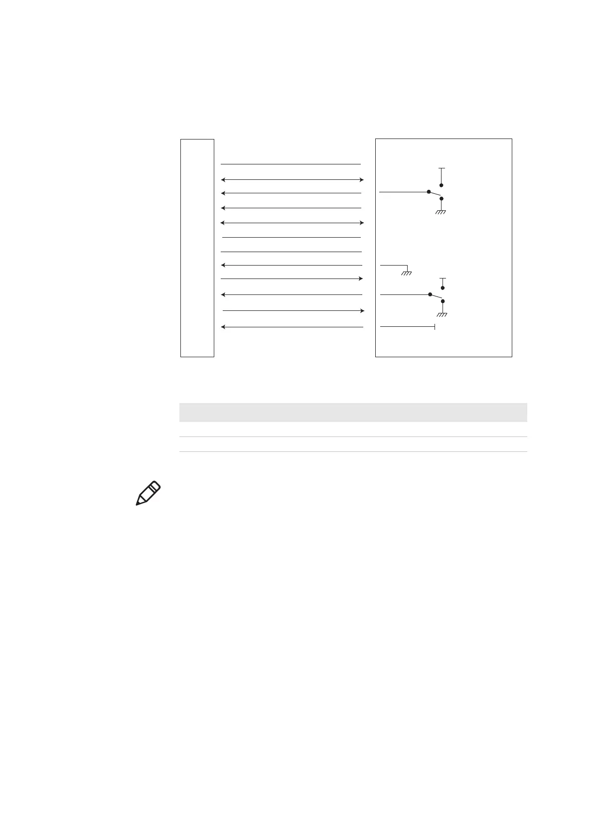
Connecting the ED40 to the Host with a USB Connection
USB Operating Mode Trig ger Detect In 2 Detect In 1 Detect In 0
Normal operation x 0 0 1
Firmware download 1 1 0 1
ED40
HOST
1
2
3
4
5
6
7
8
9
10
11
12
USB D+
Trigger
Power enable
USB D-
Do not connect
GND
Detect in 1
LED
Detect in 2
Buzzer
Detect in 0
Vcc
trigger on
Vcc
trigger o/
firmware download
Vcc
Vcc
normal operation
firmware download
Note: Intermec recommends the following for a USB connection: The differential
characteristic impedance (Z
0) of 90 Ohms ±15%, a common impedance (ZCM) of
30 Ohms ±30%, and a maximum one-way delay of 26 ns.
The D+ and D- circuit board traces which run between a transceiver and its
associated connector should have a nominal differential impedance of 90 Ohms
and together they may add an additional 4 ns of delay between the tranceivers.