Appendix D — EA30 Imager
ED40 Decode Board Integration Guide 139
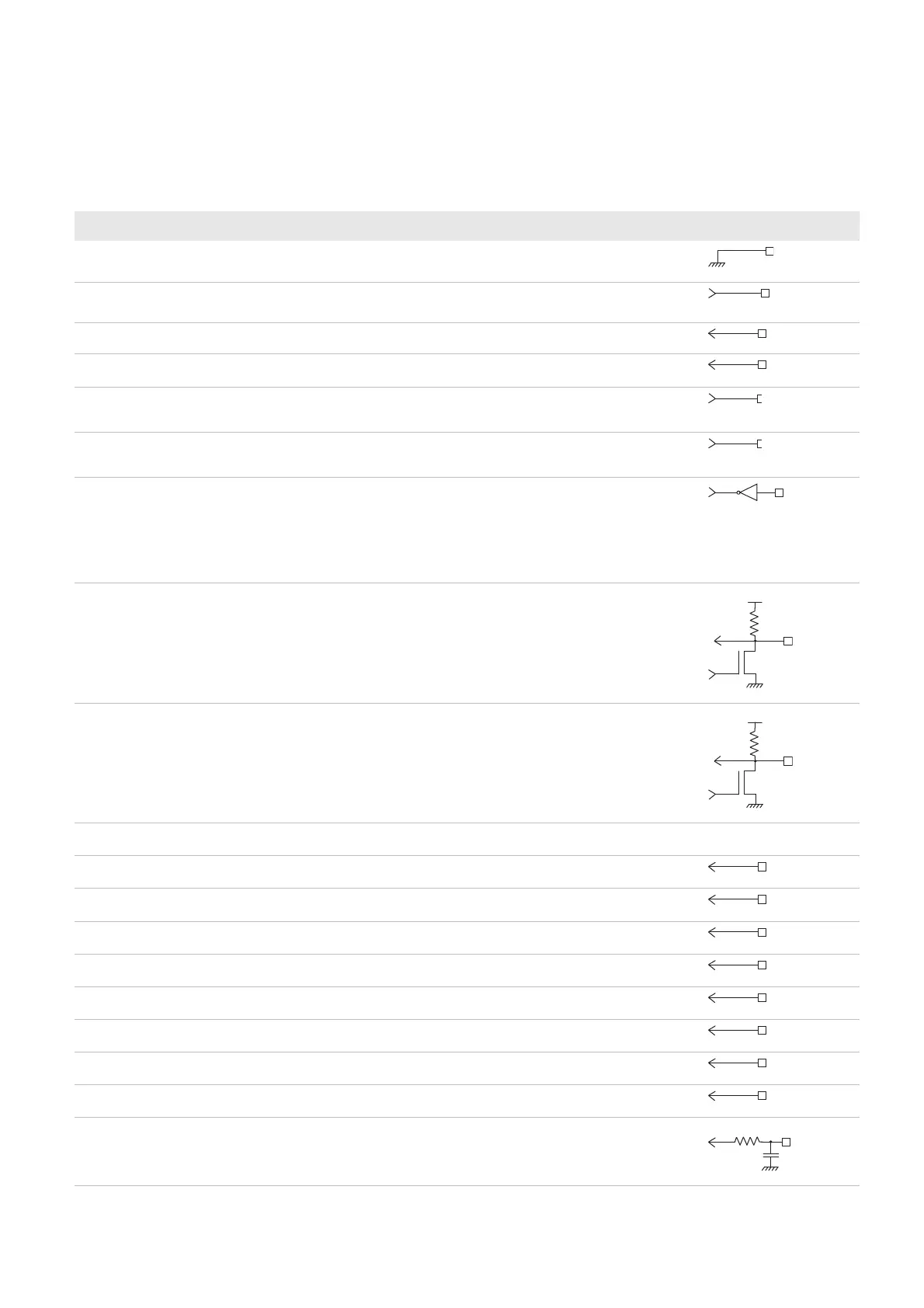
Imager Connector Contact Assignment
Contact input and output directions are relative to the decode board.
Contact Name I / O Description Electrical Equivalent
1 GND — Sensor and aimer ground
2 System_clock Output 26.67 MHz maximum input clock frequency
(60 fps)
3 Horizontal sync Input Horizontal sync signal
4 Vertical sync Input Vertical sync signal
5 Aiming beam Output 1 = Aiming beam on
0 = Aiming beam off
6 Light_ctrl/EXT_sync Output 1 = Enable lighting
0 = Disable lighting
7 Power enable Output Sensor enable control
1 = Enabled
0 = Power down
Only shuts down the sensor (does not turn off
the LEDs). The imager setup is kept.
8 SDA Input/output Serial bus data
Use the serial bus interface to program the
imager registers.
This line is pulled up to Vin_sensor by a
1.5kOhm resistor.
9 SCL Input/output Serial bus clock
Use the serial bus interface to program the
imager registers.
This line is pulled up to Vin_sensor by a
1.5kOhm resistor.
10 Vin_sensor +aimer — Sensor and aiming power
11 Data in Input Data input bit 0
12 Data in Input Data input bit 1
13 Data in Input Data input bit 2
14 Data in Input Data input bit 3
15 Data in Input Data input bit 4
16 Data in Input Data input bit 5
17 Data in Input Data input bit 6
18 data in Input Data input bit 7
19 Pixel clock Input Pixel clock output for data out