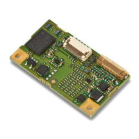
Chapter 3 — Electrical Integration
16 ED40 Decode Board Integration Guide
Electrical Interface
This section provides electrical interface information for the host connector and
imager connector.
Host Connector
The host connector is a 12-contact ZIF connector used to connect the decode
board to the host.
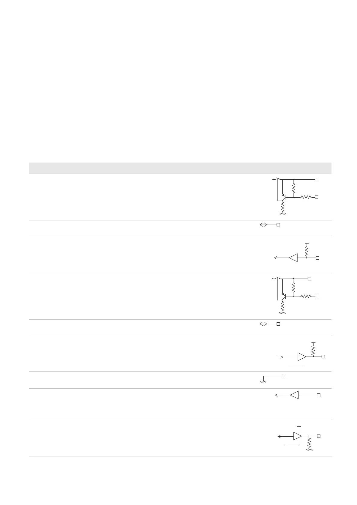
Contact Assignment
Contact input and output directions are relative to the decode board.
Contact Assignment—Host Connector
Contact I/O Name Description Electrical Equivalent
1 - Vcc 3.0 V to 5.5 V
2Input/
output
RXD/USB D+ Serial input, receive from host/USB data plus.
3 Input Trigger 0 = Start reading session.
Reads, decodes, and sends information to the
host system.
1 = Stop reading session.
Stops reading and decoding.
4 Input Power Enable 0 = On (active idle).
1 = Off, except when writing setup parameters to
non-volatile memory.
To conserve power, set contact 4 to high when not
scanning. For more information, see “Power
Enable” on page 17.
5Input/
Output
TXD/USB D- Serial output, transmission to host/USB data
minus
6 Output RTS/NC Used to request permission from the host to
transmit on TXD line (RTS/CTS hardware
protocol).
7 - GND Ground
8 Input Detect in 1 Must be connected to Vcc for an RS-232
connection.
Must be connected to ground for a USB
connection.
9 Output LED Used to drive external LED.
Contact 9 does not provide enough current (4
mA) to drive the LED. You must add a transistor
between contact 9 and the LED. For more
information, see “LED” on page 18.
47K
47K
Vcc in
Vcc
47K
Vcc
Data out
Enable
100 K
Vcc in
Data out
Enable