Appendix C — EA21 Imager
116 ED40 Decode Board Integration Guide
Imager Connector Contact Assignment
Contact input and output directions are relative to the decode board.
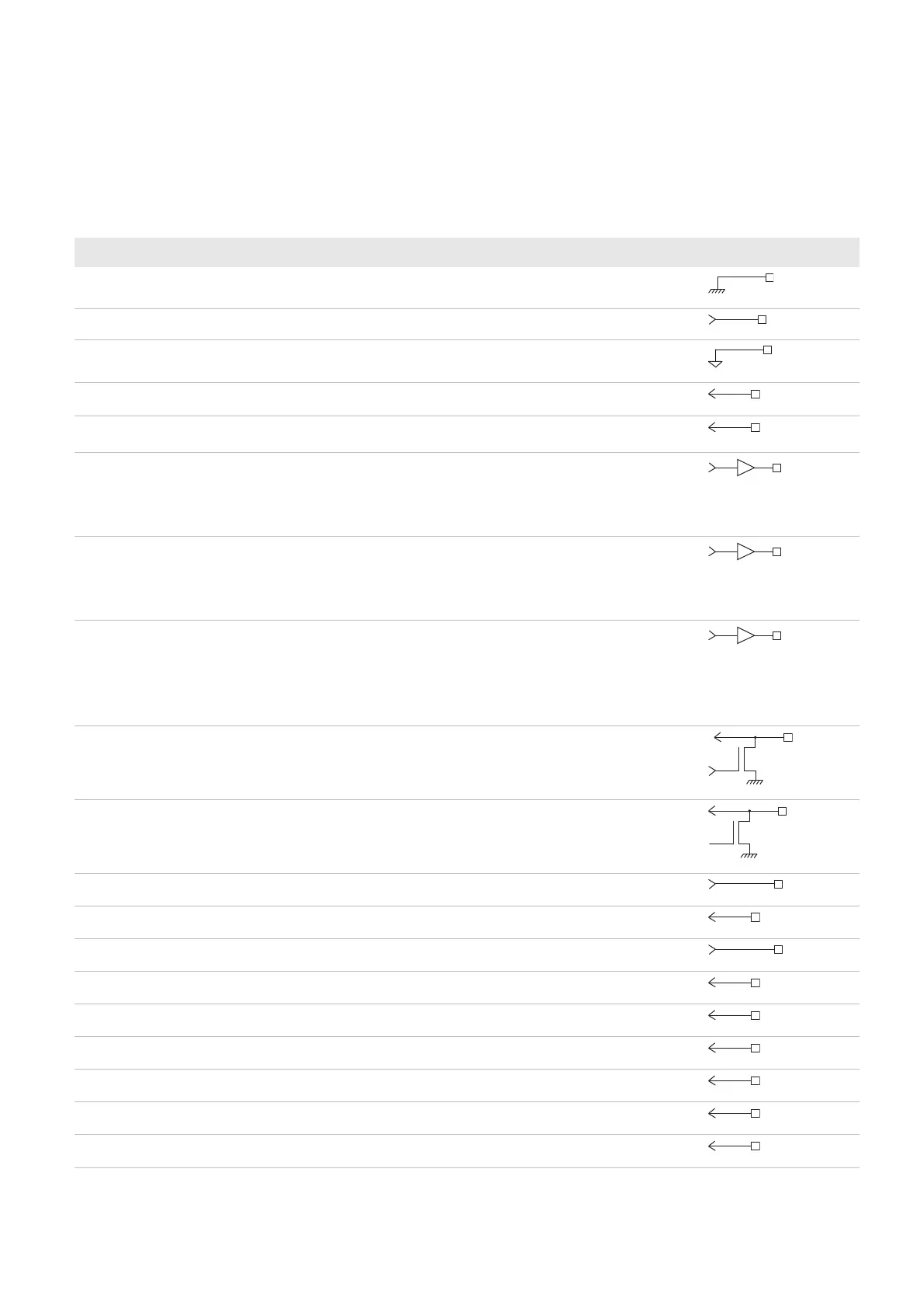
Contact Assignment—EA21 Imager Connector
Contact Name I / O Description Electrical Equivalent
1 GND_light – Lighting ground
2 master_clock output Master clock
3 GND_sensor – Sensor ground
4 horizontal sync input Horizontal sync signal
5 vertical sync input Vertical sync signal
6 laser framing/aiming
beam
output 1 = Laser framing on/aiming beam on
0 = Laser framing off/aiming beam off
(laser framing or aiming beam depends on the
imager)
7 light_ctrl output 0 = Lighting off
1 = Lighting on or pulse width modulation
(10KHz-100KHz)
Controls the intensity of the lighting LEDs.
8 power enable output Sensor enable control
1 = Enabled
0 = Power down
Only shuts down the sensor (does not turn off
the LEDs). The imager setup is kept.
9 SDA input/output Serial bus data
10 SCL output Serial bus clock
11 Vout_sensor – Sensor power supply
12 data in input Data input bit 0
13 Vout_light – LED power supply
14 data in input Data input bit 1
15 data in input Data input bit 2
16 data in input Data input bit 3
17 data in input Data input bit 4
18 data in input Data input bit 5
19 data in input Data input bit 6