Chapter 2 — Mechanical Integration
ED40 Decode Board Integration Guide 7
Ribbon Cable Connecting the Decode Board to the Host
The ribbon cable from the ED40 decode board to the host is connected to a 12-
pin ZIF, 0.5 mm (0.02 in) spacing connector with gold contacts (Manufacturer P/
N Molex 54548-1271 or JST 12FKZ-RSM1-1-TB(LF)(SN)).
For a USB connection Intermec recommends a differential characteristic
impedance (Z
0) of 90 Ohms ±15%, a common impedance (ZCM) of 30 Ohms
±30%, and a maximum one-way delay of 26 ns.
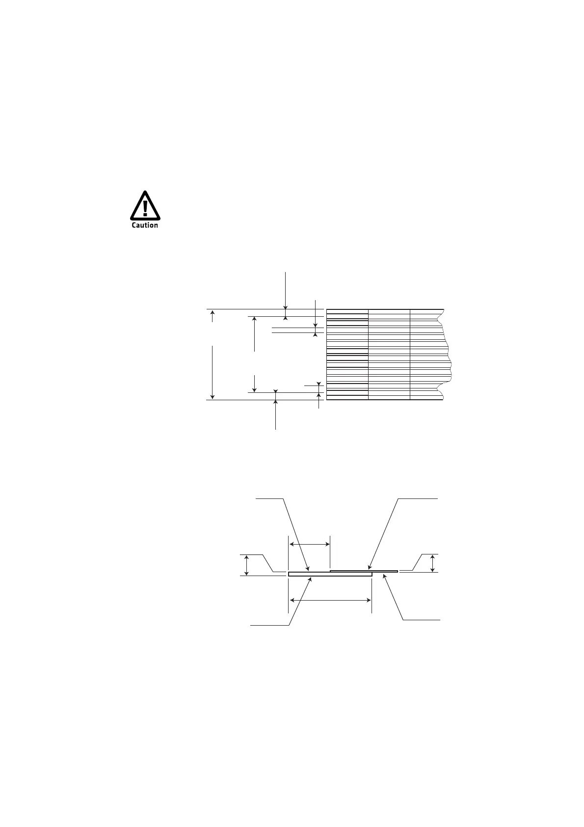
Ribbon Cable From the ED40 Decode Board to the Host: This illustration shows the top
view and side view of the ribbon cable from the ED40 decode board to the host. Intermec
recommends that you specify the resistance for the PIN 1 (Vcc) and PIN 7 (GND) conductors
to be less than 0.1 ohm.
To avoid corrosion caused by dissimilar metals, Intermec recommends
using a ribbon cable with gold plated contacts. Corrosion can create a
barrier between the connector contacts and the ribbon cable contacts and
cause the imager to stop working.
0.500 mm ± 0.100
0.020 in ± 0.004
0.35 mm ± 0.04
0.014 in ± 0.002
0.500 mm ± 0.030
0.020 in ± 0.001
0.500 mm ± 0.100
0.020 in ± 0.004
5.500 mm ± 0.030
0.217 in ± 0.001
6.500 mm ± 0.030
0.256 in ± 0.001
0.125 mm ± 0.030
0.005 in ± 0.001
0.300 mm ± 0.030
0.012 in ± 0.001
3.000 mm
0.118 in
6.000 mm
0.236 in
Reinforcing layer
Base layer
Cover layer
Conductor
Top View
Side View